- 6 -
Ensure that there is a clear line of sight to the Detector, taking care that no moving objects i.e. doors,
mechanical lifting equipment etc, will interfere with the beam path between the Detector and Prism(s).
Note: On ranges of ≥5 metres and ≤50 metres use a 50 metre Detector.
On ranges of ≥50 metres and ≤100 metres use a 100 metre Detector.
5. Prism Targeting Mode.
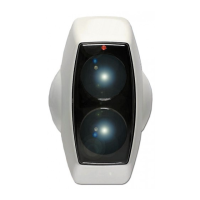
Apply power to the Detector. There is a 5 seconds pre-charge delay after power is applied to allow the internal
circuits to stabilise correctly. After this period the RED indicator will flash once to indicate that the model is a 50
metre Detector or will flash twice to indicate a 100 metre Detector.
Do not remove the detector from the wall during this action.
Mechanical alignment is provided by two adjustment thumb wheels on two sides of the Detector, positioned just
behind the Detector Head cover. Adjustment is achievable in both vertical and horizontal axis.
Find the prism(s) by adjusting the horizontal and vertical thumbwheels until the FAULT indicator is continuously
ON. The FAULT indicator will be OFF when no signal is being received. It will then flash at an incrementing rate
to determine the target position. The faster the flash rate (the stronger the signal), the nearer you are to the
target (prism). As the beam is moved across the prism the flash rate will increase, go solid and then go back to
a flash rate. A continuous LED indicates that the prism has been detected. Find the halfway point for each axis,
by counting the amount of turns of the thumbwheel it takes for the LED to go from just flashing to on, to on to
just flashing. At this point reverse the direction of rotation, and turn the thumbwheel half the amount of turns
counted.
It is essential to test that the prism(s), and not another surface, is reflecting
the signal back to the detector.
This can easily be confirmed by covering the prism(s), with a non-reflecting surface, and confirm that the
FAULT indicator changes state, either the FAULT indicator is OFF or flashing very slowly.
If an area has a large amount of reflective surface along the beam path, do not at first fit the reflector(s). When
in targeting mode ensure that the AMBER LED does not flash. Then fit the reflector(s) in a position that turns
the AMBER LED constantly on.
6. Alignment Mode.
6.1. Enabling Alignment Mode.
Do not remove the detector from the wall during this action.
Using the mode switch (See fig. 4, page 11) select Alignment Mode (Move switch to the middle position).
6.2. Adjustment in Alignment Mode.
The Detector will automatically adjust its infrared beam power and receiver sensitivity to give an optimum
receiver signal strength (100%).
The alignment progress is indicated by the colour and state of the indicator lamp on the front of the Detector.
• FLASHING ALARM (Red LED)
The Detector is receiving a high signal (>100%) and is attempting to reduce the infrared power output to
compensate.
• CONTINUOUS FAULT (After a 5 minute period of Amber LED flashing)
The Detector is not receiving a signal (0%). Go back to Prism Targeting Mode.
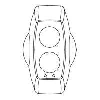
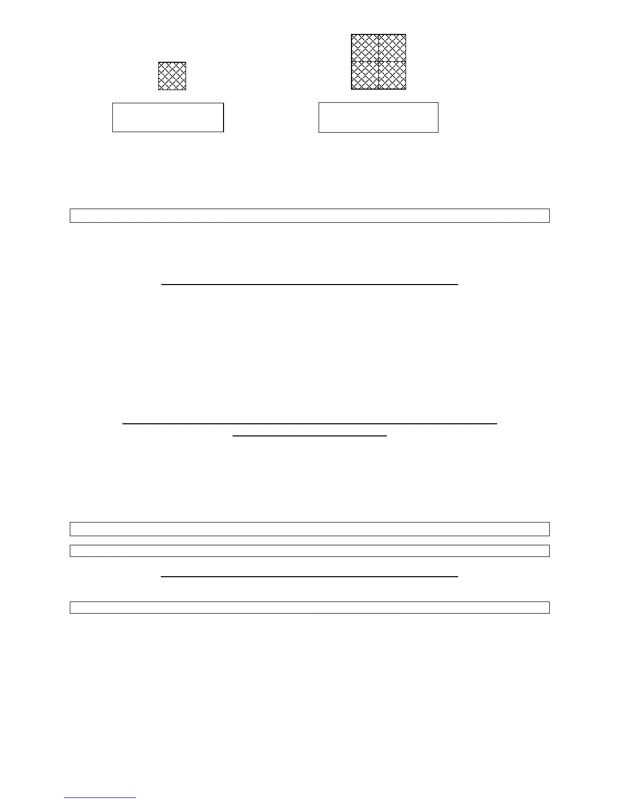
1 Reflective Prism for
the 50 metre Detector
4 Reflective Prisms for
the 100 metre Detector
 Loading...