- 8 -
6.4. Exiting Alignment Mode.
Do not remove the detector from the wall during this action.
Using the mode switch (See fig. 4 page 11) select Operating Mode (Switch will be in its lower position).
On exiting alignment mode the Detector will perform an internal calibration check. The Amber (Fault) LED will
flash once a second, for up to sixty seconds, and then go out. If this fails, which would be due to bad alignment
or either electrical/optical noise, the detector will indicate a Fault condition. In this case the alignment procedure
must be repeated.
If the internal calibration check completes satisfactory, the FAULT LED indicator will turn OFF and the fault
relay will clear. The Detector is now in normal operating mode.
Note: On the 50 metre and 100 metre Detectors, the Amber LED will flash once every 10 seconds to
indicate the beam is operational.
7. System Testing.
After successful installation and alignment the System will require testing for both alarm and fault conditions.
7.1. Fault Test.
Using a non-reflective object, quickly cover the entire prism(s).
The Detector will indicate a fault within 10 seconds by activating the FAULT LED and operating the Fault Relay.
The fault condition will automatically reset after a period not greater than 2 seconds when the obstruction is
removed.
7.2. Alarm (smoke) Test.
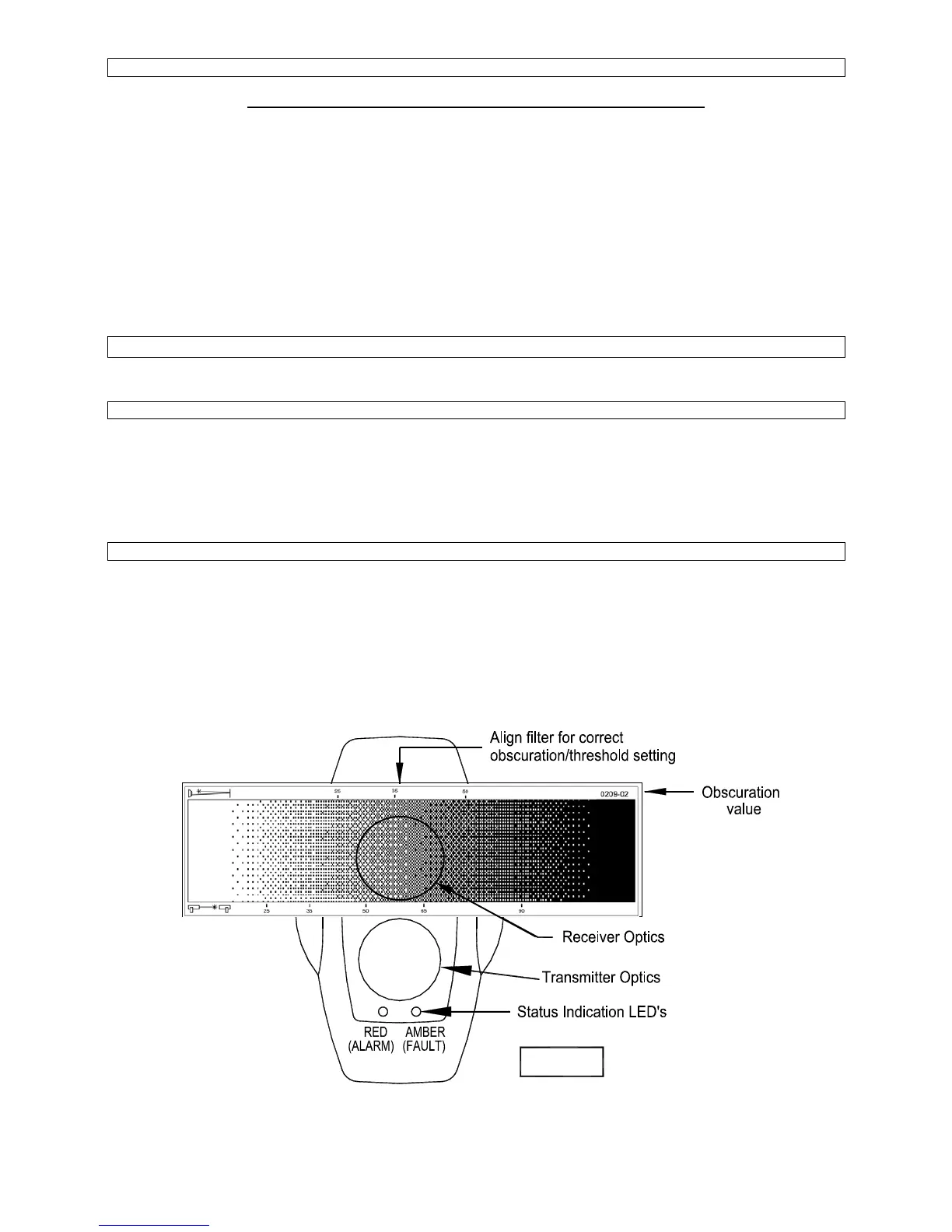
Select obscuration mark on the filter to correspond with the Detector alarm threshold (see fig. 3 below).
Place the filter over the receiver optics (Top of Detector Head − opposite end to the status indication LED’s) at
the correct obscuration value determined by the threshold selected, i.e. if a threshold of 35% has been
selected, position the filter just past the 35% obscuration value on the filter (see fig 3 below).
Take care not to cover the transmitter optics.
The Detector will indicate a fire within 10 seconds by activating the ALARM LED and operating the Fire Relay.
Fig. 3