4
“Changes or modifications not expressly approved by the party responsible for compliance could void the user's authority to
operate the equipment.”
The controller shall be located as close as practical to the engine/motor it controls and shall be within sight of the
engine/motor. The controller shall be located or protected such that it will not be damaged by water escaping from pump or
pump connections. Current carrying parts of the controller shall be not less than 12 in. (305 mm) above the floor level.
Working clearances around controller shall comply with NFPA 70, National Electrical Code, Article 110 or C22.1 or other
local codes.
The controlle
r is suitable for use in locations subject to a moderate degree of moisture, such as a damp basement. The pump
room ambient temperature shall be between 39°F (4°C) and 104°F (40°C) (If a temperature option is included, see the rating
label for maximum temperature).
The standard controller enclosure is rated NEMA 2. It is the installer's responsibility to insure that either the standard
enclosure meets the ambient conditions or that an enclosure with an appropriate rating has been provided. Controllers must
be installed inside a building and they are not designed for outside environment. The paint color may change if the
controller is exposed to ultraviolet rays for a long period of time.
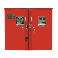
The fire pump controller shall be mounted in a substantial manner on a single incombustible supporting structure. Wall
mounted controllers shall be attached to the structure or wall using all four (4) mounting ears provided on the controller with
hardware designed to support the weight of the controller at a height not less than 12 in. (305 mm) above floor level. Floor
mounted controllers shall be attached to the floor using all holes provided on the mounting feet with hardware designed to
support the weight of the controller. The mounting feet provide the necessary 12 in. (305 mm) clearance for current carrying
parts. For seismic applications, the mounting arrangement should be rigid wall and base only. The structural engineer of
record on the project shall be responsible for anchorage details.
Note—Consult the appropriate job plans to determine controller mounting location. Controller must be mounted within view
of the engine.
Tools and Materials (all mounting):
1. Assortment of common hand tools of the type used to service electromechanical equipment.
2. Hole (conduit) punch.
3. Drill for drilling wall/floor anchor holes.
4. Hand level.
5. Tape measure.
6. Four (4) anchors with bolts and washer—if wall mount. Six (6) anchors, bolts and washers—if floor/base mount.
Wall Mount— Procedure
1. Locate bottom mounting brackets and hardware.
2. Inspect for damage.
3. Gently lay the controller on its back, using protection so the paint is not damaged. It is best to lay the controller in
a location that is out of the way from actual mounting location.
4. Attach each bracket to the bottom of the enclosure using the supplied hardware . Tighten nuts securely.
Note—Refer to the controller dimension drawing for necessary mounting dimensions.
The controller is wall mounted by using four (4) wall anchors, 2 anchors for the top ears and 2 anchors for the bottom
mounting brackets. The ears and brackets are dimensionally on the same center-line for ease in mounting.
 Loading...