6
Use #14 AWG wire minimum for all electrical connections except for battery charger connec-tions. (Battery chargers
connected to terminals 6, 8, and 11.)
On terminals 6, 8, and 11, use the following information to determine wire sizes:
Linear feet (in conduit run) from controller to terminal block
on engine
0’ to 25’ (0 to 7.62 m.)
25’ to 50’ (7.62 m. to 15.24 m.)
#10 AWG (6 mm2)
#8 AWG (10 mm2)
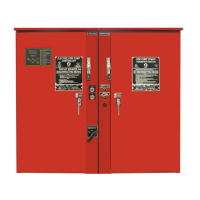
Prior to making any field connections:
1. Open door of enclosure and inspect internal components and wiring for any signs of frayed or loose wires or other
visible damage.
2. Verify that the controller information is what is required on the project:
Firetrol catalog number
Engine voltage and polarity of grounding
Incoming line voltage and frequency
Maximum system pressure
3. Project electrical contractor must supply all necessary wiring for field connections in accordance with the National
Electrical Code, local electrical code and any other authority having jurisdic-tion.
4. Refer to the appropriate field connection drawing for wiring information.
The installer is responsible for adequate protection of the fire pump controller components against metallic debris or drilling
chips. Failure to do so may cause injuries to personnel, damage the controller and subsequently void warranty.
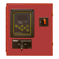
Diesel Controller with boost charger
120VAC 220/240VAC VDC Output
1.0A 1.0A
13.8V
6A 4A
1.0A 0.5A
27.6V
9A 6A
*12 amps through each battery
**10 amps through each battery
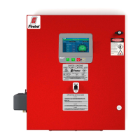
Incoming Power Connections
Diesel engine driven fire pump controllers shall be powered by a dedicated source protected by a fuse or circuit
breaker. Verify the label on the cabinet to select the correct protection. Always follow this procedure when connecting or
disconnecting the controller: Connect both batteries before connecting the AC power. Disconnect the AC power before
 Loading...