4150K and 4160K Series
14
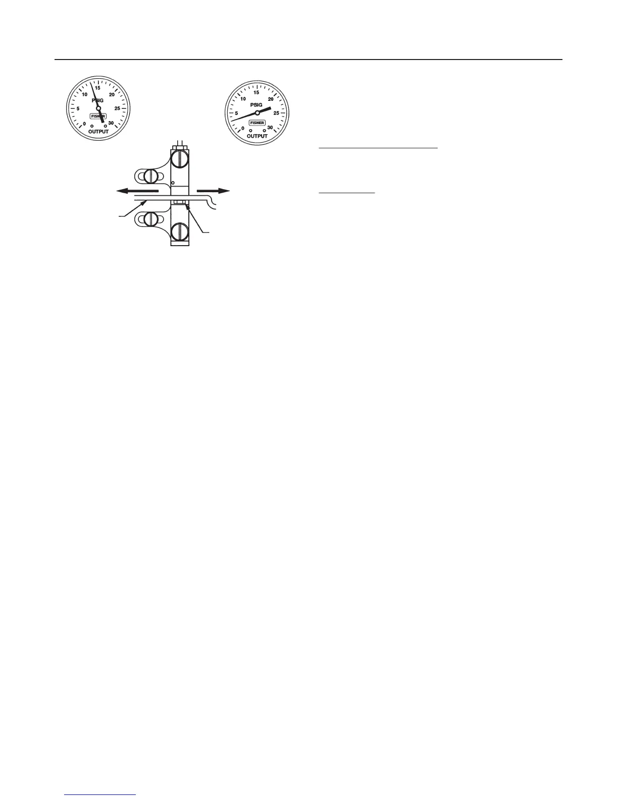
Figure 10. Reverse-Acting Controller Span Adjustment—
Proportional-Plus-Reset Controllers
IF OUTPUT IS:
ABOVE
8 TO 10 PSIG
(0.6 TO 0.7 BAR)
BELOW
8 TO 10 PSIG
(0.6 TO 0.7 BAR)
MOVE ADJUSTER
LEFT
MOVE ADJUSTER
RIGHT
FLAPPER
NOZZLE
NOTE:
3 TO 15 PSIG (0.1 TO 1.0 BAR) OUTPUT SHOWN.
FOR 6 TO 30 PSIG (0.2 TO 2.0 BAR) OUTPUT, ADJUST
VALUES AS APPROPRIATE.
A6155-1 / IL
Calibration: Anti-Reset Windup
Controllers with anti-reset windup have a differential
relief valve assembly (figure 20). This relief valve is
set at the factory to relieve at a 5 psi (0.3 bar) pres-
sure difference between the reset bellows pressure
and the proportional bellows pressure. The valve can
be adjusted to relieve from 2 to 7 psig (0.14 to 0.4
bar).
The relief valve can relieve on either rising controller
output pressure or falling controller output pressure. If
the arrow on the relief valve points toward the bottom
of the controller case as shown in figure 20, the valve
will relieve on falling output pressure. If the arrow
points in the opposite direction, the valve will relieve
on rising output pressure. The valve can be removed
and reinstalled with the arrow pointing in the opposite
direction to change the relief action.
Startup: Proportional-Plus-Reset
Controllers
(General Tuning Guidelines)
Calibrate the controller prior to this procedure.
1. Be sure that the supply pressure regulator is deliv-
ering the proper supply pressure to the controller.
2. Rotate the pressure-setting knob to the desired set
point.
3. Start with a reset setting of 0.05 minutes per repeat
(m/r) for fast processes, and 0.5 m/r for slow pro-
cesses.
4. Set the proportional band adjustment to 100 per-
cent for fast processes (example: liquid pressure or
liquid flow). For a slow process (example: tempera-
ture), calculate the percentage from the equation be-
low:
For a slow process, determine the initial proportional
band setting in percent from the following equation:
200 Allowable Overshoot
Pressure Span
+ P.B.
For example:
200 2 psig
30 psig
^ 13%
(1.3 proportional band setting)
5. Proportional Action:
Disturb the system by tapping the flapper lightly or
change the set point a small amount and check for
system cycling. If the system does not cycle then low-
er the proportional band (raising the gain) and disturb
the system again. Continue this procedure until the
system cycles. At that point, double the proportional
band setting and begin tuning the reset.
6. Reset Action:
Disturb the system. If the system does not cycle then
speed up the reset and disturb the system again. Con-
tinue this procedure until the system cycles. When the
system cycles multiply the reset time setting by a fac-
tor of three (3) and slow the reset down to the new
value. The reset is now tuned.
This tuning procedure may be too conservative for
some systems. The recommended proportional band
and reset setting should be checked for stability by
introducing a disturbance and monitoring the process
as previously described. For some applications, tighter
control may be desirable.
Differential Gap Controllers
This section describes the adjustments and proce-
dures for calibration and startup. The adjustment loca-
tions are shown in figure 5 unless otherwise specified.
The output of each controller is checked at the factory
before the instrument is shipped.
To convert a differential gap controller to a proportion-
al-only controller or vice versa, refer to the appropriate
procedure in the Maintenance section.
If the process pressure can be varied through all or
part of the sensing element range or through the two
desired switching points, use the process pressure for
calibration. If not, provide a pressure source to simu-
late the process pressure range for calibration proce-
dures.
To better understand the adjustments and overall op-
eration of the controller, refer to the Principle of Op-
eration section in this manual for differential gap con-
trollers and the schematic diagram in figure 14.