4150K and 4160K Series
26
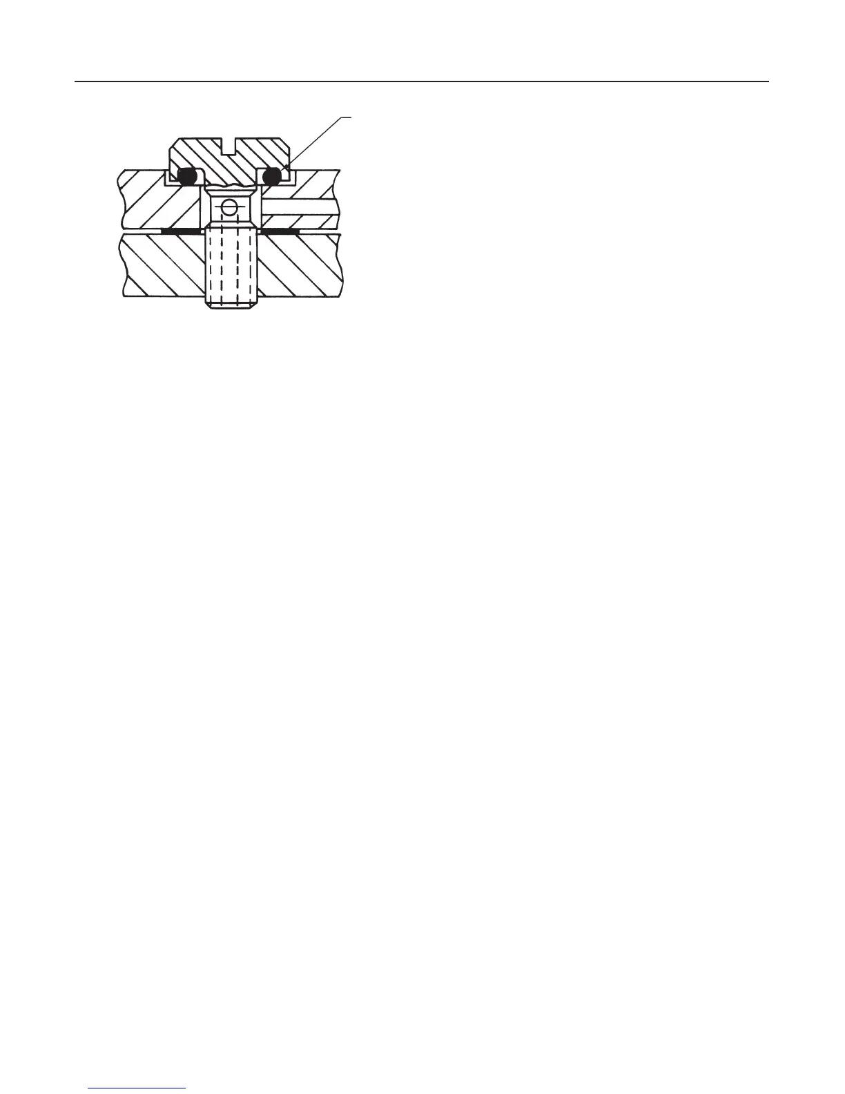
Figure 18. Bellows Screw Detail
0–RING
(KEY 55)
A6281-1 / IL
Note
The bellows screw (key 54) has an O-
ring (key 55) installed beneath the bel-
lows screw head as shown in figure 18.
Be sure this O-ring is in place before
installing the screw into the mounting
base.
8. Compress the bellows, and install them into the
mounting base (key 30). With the beam parallel with
the mounting base, secure the bellows with the bel-
lows screws (key 54).
9. After tightening the bellows screws, make sure that
the nozzle (key 57) is centered on the flapper (key 45).
10. Replace the subassembly in the case and secure
with the machine screws (key 28, figure 19 or 20).
Install the Bourdon tube if it was removed; refer to the
Replacing Bourdon Tube section if needed. Reconnect
all tubing.
11. Unscrew the supply and output gauges (key 13,
figure 19 or 20) and install new gauges with correct
ranges.
12. Check all tubing connections and the bellows ma-
chine screws for leaks, tighten as necessary. Perform
the appropriate calibration procedures.
Parts Ordering
Whenever corresponding with the sales office or sales
representative about this equipment, mention the seri-
al number of the unit. The serial number can be found
on the nameplate (key 22, figure 19). When ordering
replacement parts, also state the complete 11-charac-
ter part number of each part required as found in the
following parts list.
Parts Kits
Key Description Part Number
Controller Repair Kits
Kit contains keys 5, 9, 10, 21, 24, 45, 46, 53,
55, 56, 57, 58, 59, 60, 61, 63, 64, and 65
Standard Temperature R4150 X00L12
High Temperature R4150 X00H22
Relay Repair Kits
Kit contains keys 7, 85, 86, 87, 88, 90, 91, 92,
93, 94, 99, & 100 (Keys 99 & 100 are included
in high temperature relay kits only)
Standard Temperature RRELAYX0L12
High Temperature RRELAYX0H12
Relay Replacement Kits
Kit contains key 7 & 43 and the replacement relay
Standard Temperature RRELAYX0L22
High Temperature RRELAYX0H22
Parts List
Key Description Part Number
Assemblies (Figures 19, 20, and 23)
Case and Cover Assembly, includes keys 1, 2, & 16
Std 47B9501 X012
2 psig (0.14 bar) pressure tested case & cover 47B9501 X022
For converting controllers w/remote set point to new
case and cover assembly
Type 4151K, 4153K, and 4159K 17B9974 X012
Case and Cover Assembly with anti-reset windup
assembly, Use for converting existing Type 4160KF
and 4162KF controllers to new anti-reset windup assembly
includes keys 1, 2, 16, 127, 129, 186, & 367 thru 369
–40 to 160_ F (–40 to 71_ C) 27B9511 X012
0 to 220_ F (–40 to 104_ C) 27B9511 X022
Proportional Band Valve or Span Adjustment Assembly
Std & High Temperature, aluminum 10A9122 X032
Stainless steel construction 10A9122 X082
Reset Restriction Valve Assembly
Standard Temperature
For all except Type 4160KF & 62KF 19A4361 X012
For Type 4160KF & 62KF 19A4363 X012
Relay Assembly
(Refer to relay section of list for individual parts)
Standard Temperature 22B0463 X012
High Temp, Type 4150K, 50KS, 52K, 52KS,
57K, 60K, 62K, & 64K 22B0462 X012
w/sst instrument construction
Standard Temp 22B0463 X032
High Temp, Type 4150K, 50KS, 57K, 60K 22B0462 X022
Common Parts (Figures 19 through 22)
1 Case Ass’y, aluminum
For all 4150K and 4160K Series, std or 2 psi
(0.14 bar) pressure tested case & cover 47B9513 X012
2 Cover, Ass’y aluminum
Std 47B9512 X012
For 2 psi (0.14 bar) pressure tested
case & cover 47B9512 X022
7* Relay Gasket, for all series
Std Temp, neoprene 1C8974 03012
High Temp, silicone 1N8738 04142
*Recommended spare parts