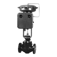
4150K and 4160K Series
15
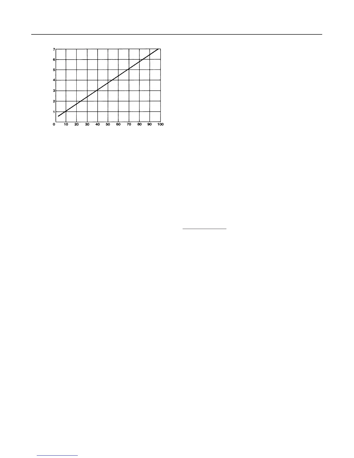
Figure 11. Differential Gap Adjustment for
Differential Gap Controllers
A2202-3 / IL
PROPORTIONAL BAND KNOB SETTING
DIFFERENTIAL GAP (PERCENT OF ELEMENT RANGE)
Adjustments
Adjustment: Set Point
The position of the pressure-setting knob determines
the location of the differential gap within the range of
the pressure sensing element. Move the pointer to the
desired pressure where the output of the controller
should switch from zero to full supply pressure with
rising process pressure (direct-acting controllers) or
with falling process pressure (reverse-acting control-
lers).
Adjustment: Proportional Band
The proportional band adjustment shown in figure 5
determines the width of the differential gap. The width
of the gap is the difference between the process pres-
sures at which the controller output will switch from
zero to full supply pressure, or from full supply pres-
sure to zero. The relationship between the proportional
band dial setting and the differential gap is shown in
figure 11.
Calibration: Differential Gap Controllers
The output of each controller is checked at the factory
before the unit is shipped. Before placing the controller
in control of a process loop, check to verify that the
controller is calibrated correctly for the application. The
controller must be connected open loop (Open loop:
The controller output pressure changes must be dead
ended into a pressure gauge).
1. Temporarily convert the differential gap controller
to a proportional-only controller by disconnecting the
proportional tubing (key 104, figure 16) from the
mounting base. Reinstall the tubing into the other con-
nection in the mounting base as shown in figure 16.
Do not invert the reversing block (key 59, figure 16).
2. Use the calibration procedures for proportional-only
controllers.
3. Upon completion of the calibration procedures, re-
install the tubing (key 104) in its original location. And,
continue with the following procedures.
Note
After reinstalling the tubing (key 104) in
step 3 a slight offset of the output pres-
sure will be noticed due to switching
from the proportional bellows to the re-
set bellows. This is because the effec-
tive area and spring rate of the two bel-
lows may not match. Performing step 5b
below adjusts for this offset.
4. Refer to figure 11 to determine the proportional
band dial setting required for the desired differential
gap.
For example, assume that a 0 to 100 psig sensing ele-
ment is being used and the controller is to switch from
zero to full supply pressure at a process pressure of
80 psig with rising process pressure and from full sup-
ply pressure to zero at 20 psig with falling pressure.
(This is for a direct-acting controller.) The differential
gap is:
80 psig * 20 psig
100 psig
100 + 60%
From figure 11, the proportional band dial setting
should be approximately 4.5; rotate the proportional
band knob to 4.5.
5. Setting the process pressure
For a Direct-Acting Controller:
a. Rotate the pressure-setting knob to the pres-
sure at which the controller output is to switch to the
upper switching point (zero to full supply pressure)
with rising process pressure. In the above example,
this pressure is 80 psig (5.5 bar).
b. Increase pressure to the sensing element while
monitoring the output pressure gauge. The controller
output pressure should switch from zero to full supply
pressure when the upper switching point is reached
with rising input pressure.
Note
If the upper switching point is not cor-
rect, adjust the nozzle to correct the er-
ror. Repeat step 5b until the input pres-
sure and upper switching point are at
the desired setting.