4150K and 4160K Series
19
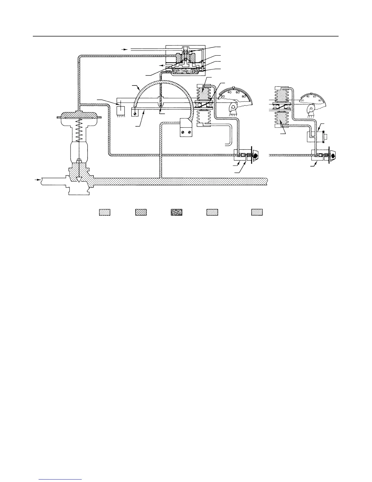
Figure 14. Schematic of Direct-Acting Proportional-Only and
Proportional-Plus-Reset Controllers
CONSTANT SUPPLY PRESSURE
EXHAUST
EXHAUST END OF RELAY VALVE
BOURDON TUBE
FIXED
PIVOT
BEAM AND
FLAPPER
NOZZLE
VENT
INLET END OF
RELAY VALVE
SMALL DIAPHRAGM
LARGE DIAPHRAGM
FIXED ORIFICE
PROPORTIONAL BELLOWS
PIVOTING CROSS SPRINGS
RESET BELLOWS
RESET
VALVE
PROPORTIONAL VALVE
PROPORTIONAL VALVE
EXHAUST
SENSED
PRESSURE
LOADING
PRESSURE
NOZZLE
PRESSURE
PROPORTIONAL
PRESSURE
RESET
PRESSURE
28A2970-A
28A2971-A
B1561-3 / IL
Controllers with Anti-Reset Windup
During a prolonged difference between set point and
the controlled variable, such as encountered with inter-
mittent control applications (e.g., batch temperature
control or wide open monitors on pressure control),
reset ramps the controller output to either zero or full
supply pressure; this condition is reset windup. When
the controlled variable crosses the set point, there will
be a delay before the controller output responds to the
change in controlled variable. Anti-reset windup mini-
mizes this delay and permits returning the controlled
variable to set point more quickly with minimal over-
shoot.
As shown in figure 15 a proportional-plus-reset con-
troller with anti-reset windup includes a differential re-
lief valve. The valve consists of two pressure cham-
bers separated by a spring-loaded diaphragm.
For the controller shown in figure 15, proportional
pressure registers rapidly on the spring side of the re-
lief valve diaphragm as well as in the proportional bel-
lows, and reset pressure registers on the opposite side
of the relief valve diaphragm. As long as controlled
pressure changes are slow enough for normal propor-
tional and reset action, the relief valve spring will keep
the relief valve diaphragm from opening. However, a
large or rapid decrease in controller pressure will
cause the relay to exhaust loading pressure from the
control device rapidly, and also from the proportional
system and spring side of the relief diaphragm. If this
decrease on the spring side of the diaphragm is great-
er than the relief valve spring setting, the diaphragm
will move off the relief valve orifice and permit the pro-
portional pressure on the opposite side of the relief
valve diaphragm to bleed rapidly into the reset bel-
lows. The anti-reset windup action also can be re-
versed to relieve with an increasing proportional pres-
sure.
Differential Gap Controllers
With a differential gap controller, feedback pressure
does not counteract the change in flapper position as it
does in a proportional-only controller. Instead, feed-
back pressure is piped through the proportional valve
to the bellows located on the side of the beam and
flapper opposite the nozzle (the lower bellows in figure
14 for direct-acting controllers). Then, as controller
output pressure increases, feedback pressure moves
the flapper closer to the nozzle to again increase con-
troller output pressure. This process continues rapidly
until the controller output pressure is at the upper
range limit. The action of a differential gap controller is
so rapid that output pressure changes from zero to
maximum as soon as the switching point is reached.
The action is similar with falling output pressure. Low-
er feedback pressure lowers the bellows pressure,
which moves the flapper away from the nozzle. This
again reduces the output pressure and continues until
the output pressure is zero.