4150K and 4160K Series
16
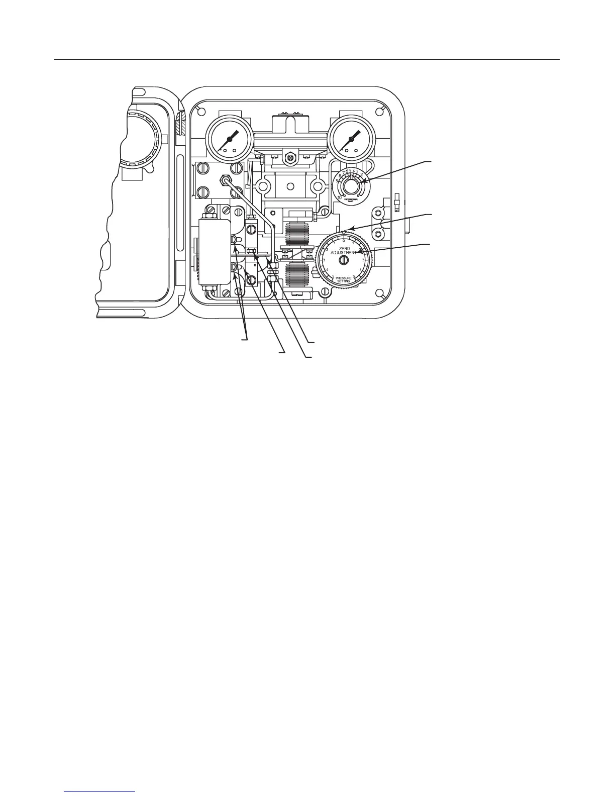
Figure 12. Transmitter Adjustment Locations
PRESSURE SETTING
DIAL (KEY 38)
ADJUSTER SCREWS (KEY 43)
CALIBRATION ADJUSTER (KEY 41)
FLAPPER (KEY 45)
NOZZLE (KEY 57)
SPAN
ADJUSTMENT KNOB
ZERO ADJUSTMENT KNOB
(KEY 36)
48B6004-B
A6039-3 / IL
c. With falling input pressure, the output should
switch from full supply pressure back to zero when the
lower switching point is reached.
Reverse-acting controllers produce the opposite re-
sponse.
6. Vary the process pressure and observe the switch-
ing points. Widen or narrow the differential gap by ro-
tating the proportional band knob, then repeat the
above steps.
If the output is within the limits stated, refer to the
startup procedures in this section. If the output pres-
sure cannot be adjusted within the limits stated, refer
to the maintenance procedures.
Startup: Differential Gap Controllers
Calibrate the controller prior to this procedure.
1. Be sure that the supply pressure regulator is deliv-
ering the proper supply pressure to the controller.
2. Adjust the proportional band knob for the proper
differential gap (see figure 11).
3. If the controller is used in conjunction with a control
valve, slowly open the upstream and downstream
manual shutoff valves, and close the bypass valves.
4. To change the differential gap, perform steps 1
through 4 of the calibration for differential gap control-
lers procedure.
Transmitter Operation
This section describes the adjustments and proce-
dures for calibration and startup. Refer to figure 12 for
the adjustment locations. All adjustments must be
made with the cover open. When the adjustments and
calibration procedures are complete, close and latch
the cover.
To better understand the adjustments and overall op-
eration of the transmitter, refer to the Principle of Op-
eration section in this manual for transmitters. Refer
also to the schematic diagram in figure 14.
Adjustments
Adjustment: Zero
The pressure-setting dial is marked ZERO ADJUST-
MENT PRESSURE SETTING. Zero is in the center of
the dial, and the pressure values increase to the right
and left of the center as shown in figure 12. To set the
zero, rotate the pointer around the pressure setting