4150K and 4160K Series
8
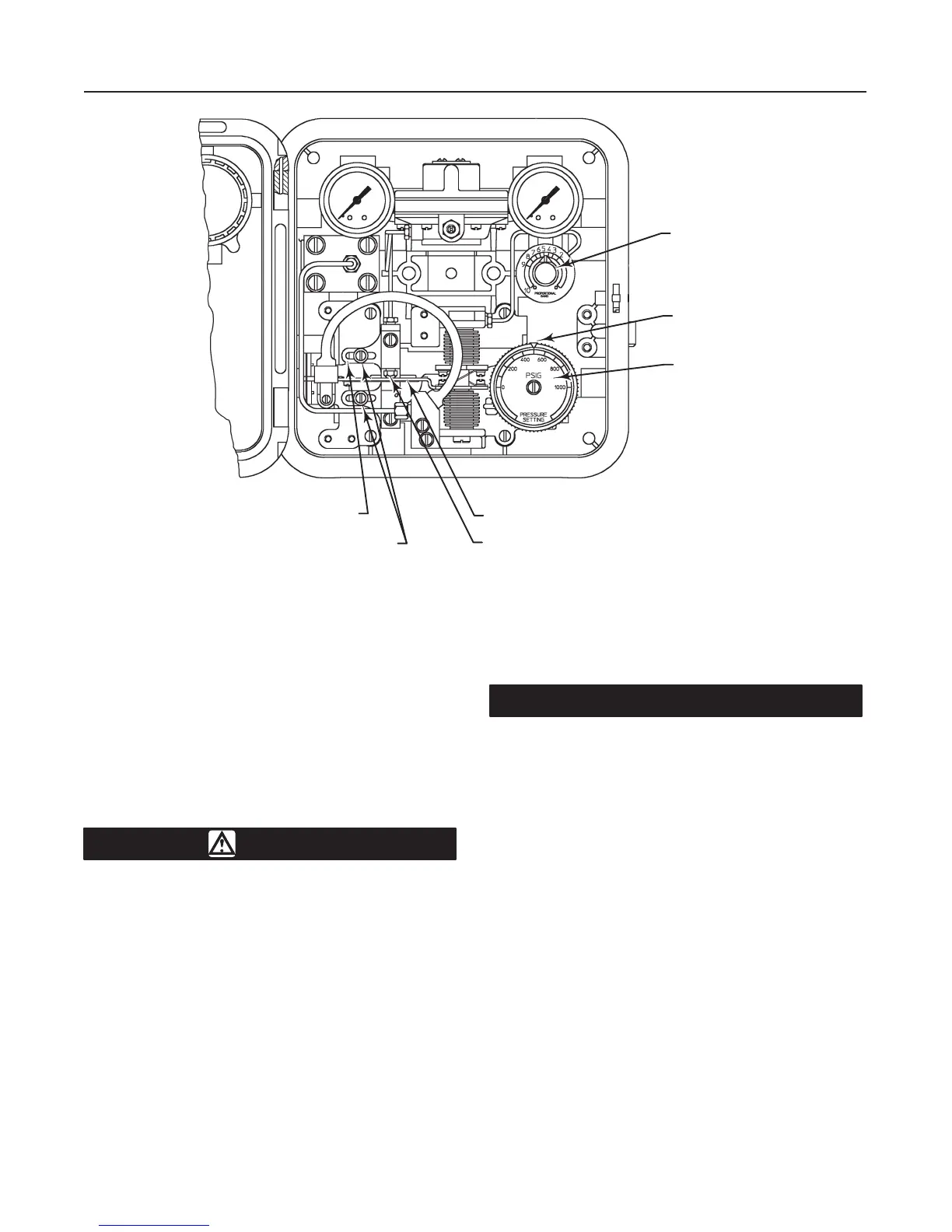
Figure 5. Proportional-Only Controller Adjustment Locations
PROPORTIONAL BAND
ADJUSTMENT KNOB
PRESSURE-SETTING KNOB
(KEY 36)
PRESSURE-SETTING
DIAL (KEY 38)
FLAPPER (KEY 45)
NOZZLE (KEY 57)
CALIBRATION ADJUSTER (KEY 41)
ADJUSTER SCREWS (KEY 43)
48B6003-A
A6038-1 / IL
cess pressure line in a straight section of pipe approxi-
mately 10 pipe diameters from the valve but away
from bends, elbows, and areas of abnormal fluid velo-
cities. For pressure-reducing service, the process line
must be connected downstream of the valve. For pres-
sure-relief service, the process pressure line must be
connected upstream of the control valve. Install a
needle valve in the process pressure line to dampen
pulsations.
Vent Assembly
WARNING
If a flammable, toxic, or reactive gas is
to be used as the supply pressure me-
dium, personal injury or property dam-
age could result from fire or explosion
of accumulated gas or from contact with
a toxic, or reactive gas. The instrument
case and cover assembly does not form
a gas-tight seal, and when the assembly
is enclosed, a remote vent line, ade-
quate ventilation, and necessary safety
measures should be used. A remote
vent pipe alone cannot be relied upon to
remove all hazardous gas. Vent line pip-
ing should comply with local and re-
gional codes and should be as short as
possible with adequate inside diameter
and few bends to reduce case pressure
buildup.
CAUTION
When installing a remote vent pipe, take
care not to overtighten the pipe in the
vent connection. Excessive torque will
damage the threads in the connection.
The vent assembly (key 15, figure 3) or the end of a
remote vent pipe must be protected against the en-
trance of all foreign matter that could plug the vent.
Use 1/2-inch (13 mm) pipe for the remote vent pipe, if
one is required. Check the vent periodically to be cer-
tain it has not become plugged.
Controller Operation
Proportional-Only Controllers
This section describes the adjustments and proce-
dures for calibration and startup. Adjustment locations
are shown in figure 5 unless otherwise specified. All
adjustments must be made with the cover open. When