4150K and 4160K Series
4
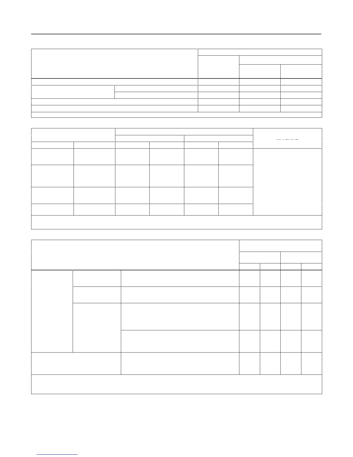
Table 2. Available Configurations
TYPE NUMBER
(1)
Bourdon Tube
Bellows Sensing Element
ensing Element
(Gauge Pressure
Only)
Gauge
Pressure
Differential
Pressure
Proportional-only controller 4150K 4152K 4154K
p
p
Without anti-reset windup 4160K 4162K 4164K
Proportional-plus-reset controller
With anti-reset windup 4160KF 4162KF - - -
Differential gap controller 4150KS 4152KS - - -
Transmitter 4157K 4158K 4155K
1. The suffix R is added to the type number of a construction specified for reverse action.
Table 3. Bourdon Tube Pressure Ranges and Materials
MAXIMUM ALLOWABLE STATIC PRESSURE
(2)
LIMITS
(3)
PRESSURE RANGES
Standard With Optional Travel Stop
(4)
MATERIAL
Psig Bar Psig Bar Psig Bar
0 to 30
0 to 60
0 to 100
0 to 2.0
0 to 4.0
0 to 7.0
30
60
100
2.0
4.0
7.0
48
96
160
3.3
6.6
11
0 to 200
0 to 300
0 to 600
(5)
0 to 1000
(5)
0 to 14
0 to 20
0 to 40
0 to 70
200
300
600
1000
14
20
40
70
280
420
720
1200
19
29
50
83
316 stainless steel
0 to 1500
(5)
0 to 3000
0 to 5000
0 to 100
0 to 200
0 to 350
1500
3000
5000
100
200
350
1650
3300
5500
115
230
380
0 to 8000
0 to 10.000
0 to 550
0 to 700
8000
10,000
550
700
8000
10,000
550
700
1. Range marked on Bourdon tube may be in kPa (1 bar = 100 kPa)
2. This term is defined in ISA Standard S51.1-1979.
3. Bourdon tube may be pressurized to limit shown without permanent zero shift.
4. With travel stop set at 110% of the range.
5. These Bourdon tubes are also available in K-Monel for sour gas service.
Table 4. Bellows Pressure Ranges and Materials
MAXIMUM ALLOWABLE STATIC
PRESSURE
(1)
LIMITS
(2)
PRESSURE RANGES
Brass
Construction
Stainless Steel
Construction
Psig Bar Psig Bar
Vacuum
0 to 60 inch wc (0 to 150 mbar)
0 to 10 inch Hg (0 to 340 mbar)
0 to 30 inch Hg (0 to 1.0 bar)
20
40
40
1.6
2.8
2.8
---
---
100
---
---
6.9
Compound Pressure
30 inch wc vac. to 30 inch wc (75 mbar vac. to 75 mbar)
15 inch Hg vac. to 7.5 psig (500 mbar vac. to 500 mbar)
30 inch Hg vac. to 15 psig (1.0 bar vac. to 1.0 bar)
20
40
40
1.4
2.8
2.8
---
100
100
---
6.9
6.9
Gauge Pressure
Positive pressure
0 to 60 inch wc (0 to 150 mbar)
0 to 100 inch wc
(3)
(0 to 250 mbar)
0 to 140 inch wc
(4)
(0 to 350 mbar)
0 to 5 psig (0 to 0.35 bar)
0 to 7.5 psig (0 to 0.5 bar)
20
20
40
40
40
1.4
1.4
2.8
2.8
2.8
---
---
---
---
---
---
---
---
---
---
0 to 10 psig (0 to 0.7 bar)
0 to 15 psig (0 to 1.0 bar)
0 to 20 psig (0 to 1.4 bar)
0 to 30 psig (0 to 2.0 bar)
40
40
40
40
2.8
2.8
2.8
2.8
---
100
---
100
---
6.9
---
6.9
Differential Pressure
(5)
0 to 80 inch wc (0 to 300 mbar)
0 to 10 psi (0 to 0.7 bar)
0 to 20 psi (0 to 1.4 bar)
0 to 30 psi (0 to 2.0 bar)
20
40
40
---
1.4
2.8
2.8
---
---
---
---
100
---
---
---
6.9
1. This term is defined in ISA Standard S51.1-1979.
2. Bellows may be pressured to limit shown without permanent zero shift.
3. Type 4158K transmitter only.
4. Except Type 4158K transmitter.
5. The overrange limit for these sensing elements is a differential pressure equal to the maximum allowable static pressure limit.