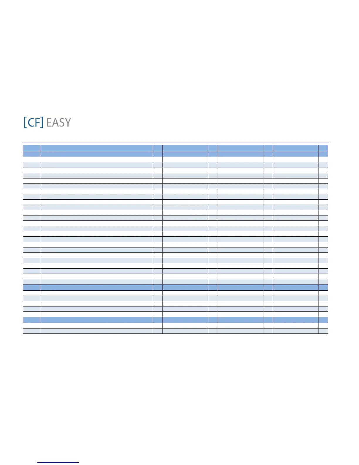
A01 Probe P1 configuration - 1-Suction pressure (0-5V) L2 1-Suction pressure (0-5V) L2 1-Suction pressure (0-5V) L2
A02 Start of scaling for probe 1 (0-5V) bar 0.0 L2 0.0 L2 0 L2
A03 End of scaling for probe 1 (0-5V) bar 15.0 L2 15.0 L2 15.0 L2
A04 Probe P1 calibration bar 0.0 L2 0.0 L2 0.0 L2
A05 Probe P1 reading error delay (P1C=0-5V) min 5.0 L2 5.0 L2 5.0 L2
A06 Probe P2 configuration - 2-Mid-coil pressure (0-5V) L2 2-Mid-coil pressure (0-5V) L2 2-Mid-coil pressure (0-5V) L2
A07 Start of scaling for probe 2 bar 0.0 L2 0.0 L2 0.0 L2
A08 End of scaling for probe 2 bar 35.0 L2 35.0 L2 35.0 L2
A09 Probe P2 calibration bar 0.0 L2 0.0 L2 0.0 L2
A10 Probe P2 reading error delay (P2C=0-5V) min 0 L2 0 L2 0 L2
A11 Probe P3 configuration - 1-Discharge Line Temperature L2 1-Discharge Line Temperature L2 1-Discharge Line Temperature L2
A12 Probe P3 calibration °C 0.0 L2 0.0 L2 0.0 L2
A13 Probe P4 configuration - 0-Not used L2 3-Vapour inlet Temp (NTC10K) L2 0-Not used L2
A14 Probe P4 calibration °C 0.0 L2 0.0 L2 0.0 L2
A15 Probe P5 configuration - 0-Not used L2 4-Vapour outlet Temp (NTC10K) L2 0-Not used L2
A16 Probe P5 calibration °C 0.0 L2 0.0 L2 0.0 L2
A17 Probe P6 configuration - 1-Ambient temp (NTC10K) L2 1-Ambient temp (NTC10K) L2 1-Ambient temp (NTC10K) L2
A18 Probe P6 calibration °C 0.0 L2 0.0 L2 0.0 L2
A19 Probe P7 configuration - 0-Not used L2 0-Not used L2 0-Not used L2
A20 Probe P7 calibration °C 0.0 L2 0.0 L2 0.0 L2
A21 Delay before activating probe error sec 0 L2 0 L2 0 L2
B01 Measurement unit for pressure 0-bar L2 0-bar L2 0-bar L2
B02 Measurement unit for temperature 0-°C L2 0-°C L2 0-°C L2
B03 Remote display visualization - 0 - (P1) L2 0 - (P1) L2 0 - (P1) L2
C01 Compressor cut in pressure setpoint bar 4.0 L1 1.0 L1
C02 Compressor cut out pressure setpoint bar 2.0 L1 0.3 L1
C03 Minimum setpoint for suction pressure bar 0.3 L2 0.7 L2 0.6 L2
C04 Maximum setpoint for suction pressure bar 6.3 L2 5.6 L2 6.3 L2
C05 Compressor regulation probe selection - 1-Suction pressure probe L2 1-Suction pressure probe L2 1-Suction pressure probe L2
![FISCHER [CF] EASY](https://data.easymanua.ls/products/636208/200x200/fischer-cf-easy.webp)