427939
11
4 PROGRAM STEPS
5 COMPONENT TESTING PROCEDURES
5.1 Motor Testing
5.1.1 Testing at the Control Panel
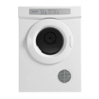
5.1.1.1 DE50F56AW1
Measuring at the timer terminals, between terminal 2 the Orange wire and terminal 5 the Blue wire
the resistance should be between 65-73 depending which motor is fitted.
Then measure between terminal 2 the Orange wire and terminal 3 the White wire the resistance
should be between 65-73 depending which motor is fitted.
Note: the timer must be in the off position.
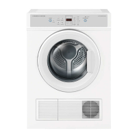
5.1.1.2 DE50F56A2 Push to Start.
Measuring at the timer terminals, between terminal B3 the Orange wire and terminal D1 the Purple
wire the resistance should be between 65-73 depending which motor is fitted.
Then measure between terminal B3 the Orange wire and terminal D2 the White wire the resistance
should be between 65-73 depending which motor is fitted.
Note: the timer must be in the off position.
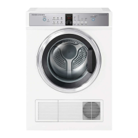
5.1.1.3 DE50F56EW
Measuring at the controller module terminals, between terminal P201 the Orange wire and terminal
P203 the Blue wire the resistance should be between 65-73 depending which motor is fitted.
Then measure between terminal P201 the Orange wire and terminal p204 the White wire the
resistance should be between 65-73 depending which motor is fitted.
5.1.2 Testing – At Motor
Orange – White = 65-73 ± 7%
Orange – Blue = 65-73 ± 7%
Blue – White = 130-146 ± 7%
Measurements dependent on which
motor is fitted.
5.2 NTC Testing / Door Switch / Heater & Thermostat
Testing at the Control Panel
5.2.1 NTC Located in Exhaust Duct DE50F56EW:
Measure at the PCB across P103-3 and P103-4 on the PCB edge connector with the harness
connected. The resistance should be 19.5k @ 25
O
C.
 Loading...