Type 1032
3
WARNING
To avoid personal injury or property
damage caused by bursting of pressure-
retaining parts, be certain the cylinder
pressure does not exceed the pressure
limits listed in table 1. Use pressure-lim-
iting or pressure-relieving devices to
prevent the cylinder pressure from ex-
ceeding these limits.
If hoisting the valve and actuator assem-
bly or the actuator by itself, take precau-
tions to prevent personnel from being
injured in case the hoist or sling slips
unexpectedly. Refer to table 2 for actua-
tor weights. Carefully position the sling
to prevent damage to tubing or any ac-
cessories.
Actuator Mounting
Use the following steps to connect a valve and actua-
tor that have been ordered separately.
1. Place the actuator and the valve in the required
orientation.
2. Check the valve and actuator mounting surfaces,
shaft coupler and valve shaft for possible discrepan-
cies.
3. Position the shaft coupler (if furnished loose) on the
valve shaft. Then, insert the square end of the coupler
into the square hole of the actuator drive. On certain
valve/actuator/coupler combinations, it is necessary to
use a shim or adaptor (furnished) in the square end of
the coupler in the actuator drive. The actuator is usual-
ly mounted parallel with the run of pipe. However, the
actuator can be mounted in any position.
4. Tighten all bolts and nuts evenly, taking care to
center the actuator on the valve shaft.
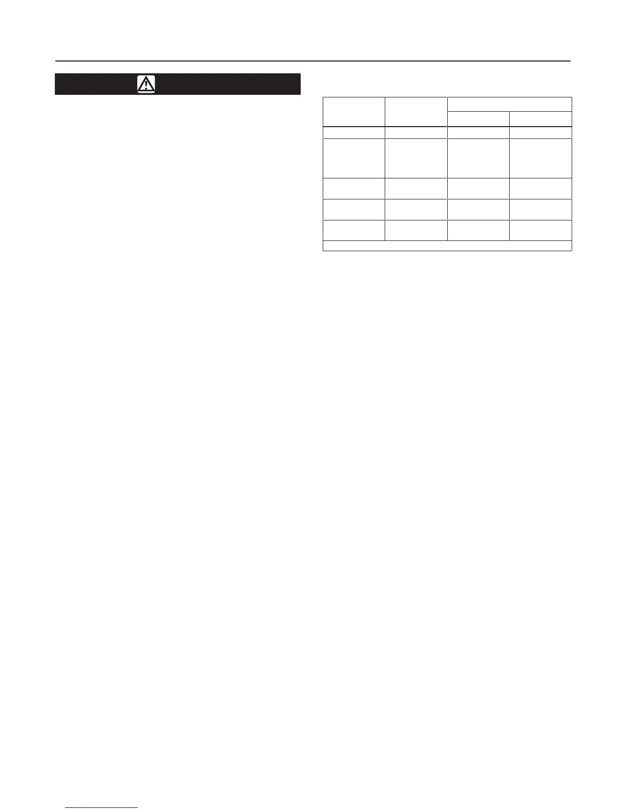
5. Refer to table 3 for valve mounting bracket to ac-
tuator bolt torques.
Table 3. V
alve Mounting Bracket
to Actuator Bolt Torque
ACTUATOR
ACTUATOR
BOLT TORQUE
MODEL
NUMBER
(1)
MOUNTING
HOLE SIZE
Lbfft Nm
45
1/4-20 UNC
4 5
70
130
185
280
5/16-18 UNC
8 11
425A
680A
3/8-16 UNC
15 20
1125
1370
1/2-13 UNC
31 42
2585
4580
3/4-10 UNC
74 100
1. Applies to both double-acting and spring-return models.
Because there are many valve and actuator combina-
tions, it is not practical to include detailed instructions
on each combination. Mountings are designed as sim-
ple as possible to keep installations easy to perform.
Travel Stop Adjustment
Type 1032 actuators are shipped from the factory with
the travel stops adjusted for approximately 90 degrees
rotation. Generally, it is necessary to make slight stop
adjustments once the actuator is installed on the
valve.
Refer to figures 10 and 11 for location of the actuator
travel stops.
Loosen the actuator travel stop lock nuts (key 10), and
adjust the travel stop adjustment bolts (key 9) to en-
sure clearance of 0.01-0.040 inch (0.3-1.0 mm) be-
tween the valve internal stops and the disk.
Loading Connection
1. Various accessories such as solenoid valves, limit
switches, and positioners may be used with these ac-
tuators. If an accessory is used, be sure that the ac-
cessory is properly connected to the actuator. If an
accessory was ordered as part of the valve and actua-
tor assembly, the pressure connection from the acces-
sory to the actuator will normally be made at the
factory.
2. Connect the supply pressure to the accessory be-
ing used or to the appropriate pressure port in the ac-
tuator. Markings are cast into the actuator adjacent to
the pressure connections as to whether supply pres-
sure forces the pistons together or apart.
3. When the valve and actuator assembly is com-
pletely installed, check for correct action (air-to-open
or air-to-close) on spring-return actuators. For suc-
cessful operation, the actuator and valve shaft must
move smoothly in response to supply pressure
changes in the pressure cylinder.