Type 1032
4
Startup
When the valve and actuator assembly are first put
into service, slight leakage past the piston O-rings
might be detected. This is due to the O-rings having
been held in one position tending to cause a ‘‘set’’ in
the O-ring. In such cases, operate the actuator
through several cycles, thereby energizing the O-rings
and resulting in a ‘‘re-seating’’.
The stroking speed will be determined by a number of
factors, including the distance from the pressure
source, supply line size, supply line pressure, acces-
sories, torque requirement of the valve, and size of the
actuator. Due to the interaction of these variables, it is
difficult to specify a normal stroking speed.
Principle of Operation
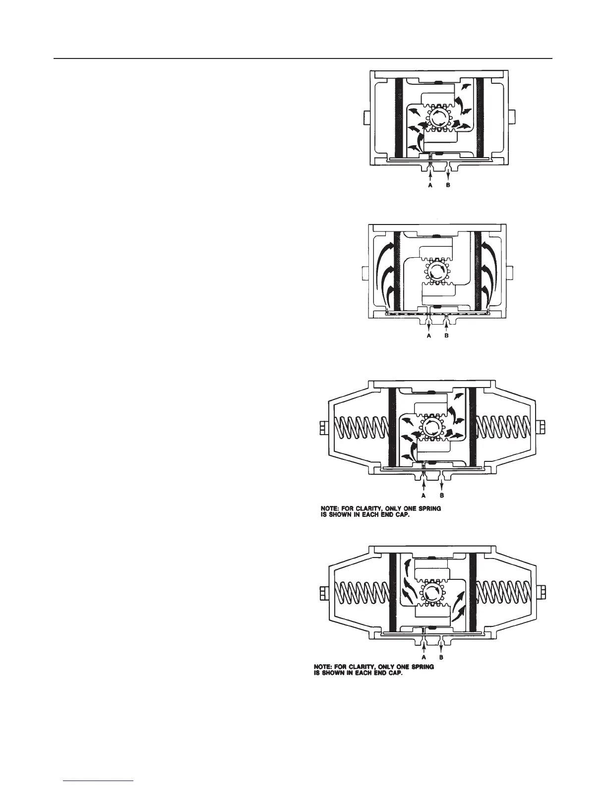
Double-Acting Actuators
For counterclockwise output rotation, refer to figure 2.
With actuator pistons installed as shown in figure 2,
supply pressure is applied to port A which forces the
pistons apart. The linear travel of the pistons is con-
verted to a counterclockwise rotation of the pinion and
valve shaft by the rack-to-pinion connection. The vol-
ume on top of each piston is exhausted through
port B.
For clockwise output rotation, refer to figure 3. With
actuator pistons installed as shown in figure 3, supply
pressure is applied to port B which forces the pistons
together. The linear travel of the pistons is converted
to a clockwise rotation of the pinion and valve shaft by
the rack-to-pinion connection. The volume between
the pistons is exhausted through port A.
Spring-Return Actuators
For counterclockwise output rotation, refer to figure 4.
With actuator pistons installed as shown in figure 4
(fail-closed action for valves with clockwise to close
disk rotation), supply pressure is applied to port A.
This pressure forces the pistons apart, compresses
the springs, and opens the valve. The linear travel of
the pistons is converted to a counterclockwise rotation
of the pinion and valve shaft by the rack-to-pinion con-
nection. The volume on top of each piston is ex-
hausted through port B. Upon loss or removal of sup-
ply pressure, the compressed springs move the
pistons together and close the valve.
Figure 2. Double-Acting Actuator with
Counterclockwise Output Rotation
A5818 / IL
Figure 3. Double-Acting Actuator with
Clockwise Output Rotation
A5819 / IL
Figure 4. Spring-Return Actuator with
Counterclockwise Output Rotation
A5820 / IL
Figure 5. Spring-Return Actuator with
Clockwise Output Rotation
A5821 / IL