Type 1032
5
For clockwise output rotation, refer to figure 5. With
actuator pistons installed as shown in figure 5 (fail-
open action for valves with clockwise to close disk
rotation), the supply pressure is applied to port A. This
pressure forces the pistons apart, compresses the
springs, and closes the valve. The linear travel of the
pistons is converted to a clockwise rotation of the pin-
ion and valve shaft by the rack-to-pinion connection.
The volume on top of each piston is exhausted
through port B. Upon loss or removal of supply pres-
sure, the compressed springs move the pistons to-
gether and open the valve.
Maintenance
Actuator parts are subject to normal wear and must be
inspected and replaced as necessary. The frequency
of inspection and replacement depends upon the se-
verity of service conditions. Instructions are given in
subsequent sections for disassembly and assembly of
the actuator.
Because of the care Fisher takes in meeting all
manufacturing requirements (heat treating, dimension-
al tolerances, etc.), use only replacement parts
manufactured by Fisher.
WARNING
Avoid personal injury from sudden re-
lease of process pressure. Before per-
forming any maintenance operations:
Disconnect any operating lines pro-
viding air pressure, or a control signal
to the actuator. Be sure the actuator
cannot suddenly open or close the
valve.
Use bypass valves or completely
shut off the process to isolate the valve
from process pressure. Relieve process
pressure on both sides of the valve.
Drain the process media from both
sides of the valve.
Vent the power actuator loading
pressure and relieve any actuator spring
precompression.
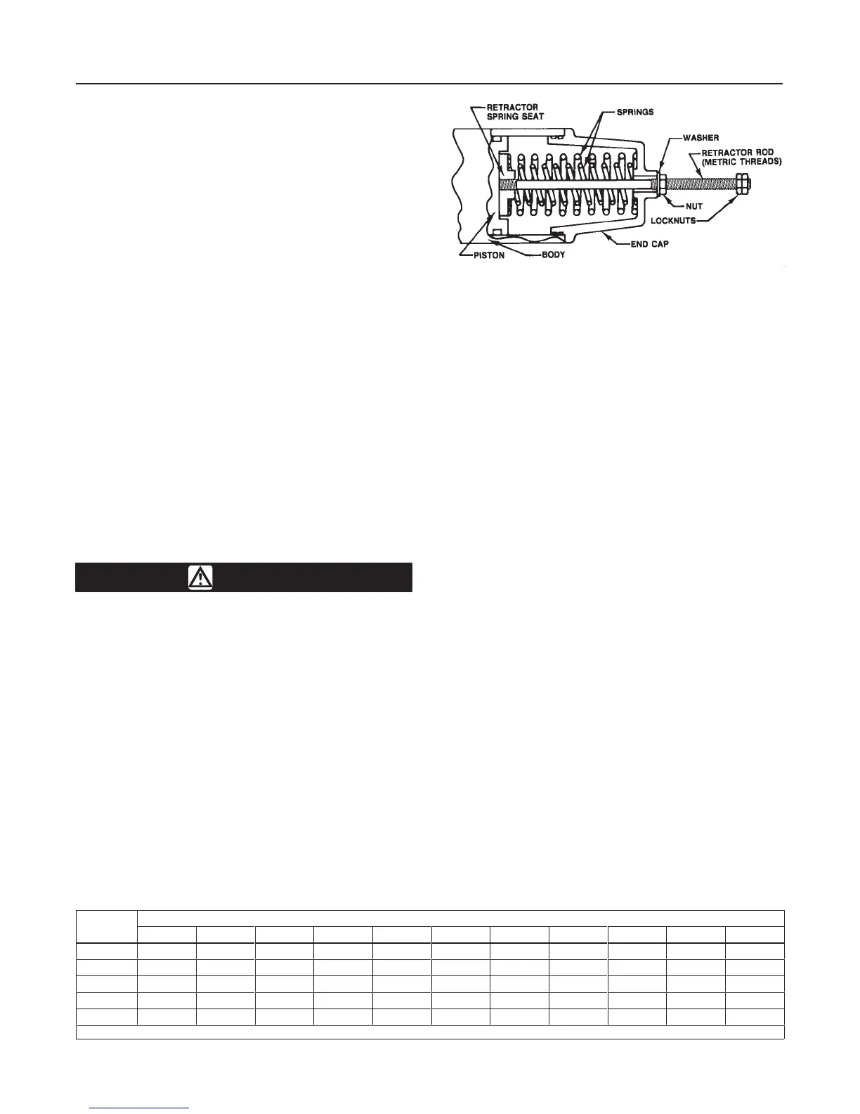
Figure
6. Spring-Return Actuator End Cap
with Retractor Rod Installed
A5833-1 / IL
Use lock-out procedures to be sure
that the above measures stay in effect
while you work on the equipment.
Disassembly
The following procedure describes how the actuator
can be completely disassembled. When inspection or
repairs are required, perform only those steps neces-
sary to accomplish the task. Key numbers referenced
in the following steps are shown in figure 10 for
double-acting actuators and in figure 11 for spring-re-
turn actuators unless otherwise indicated. Disassem-
bly procedures are identical for both double-acting and
spring-return actuators except for removal of the end
caps (key 4).
1. Isolate the control valve from the line pressure, re-
lease pressure from both sides of the valve body, and
drain the process media from both sides of the valve.
If using a power actuator, also shut-off all pressure
lines to the power actuator, release all pressure from
the actuator. Use lock-out procedures to be sure that
the above measures stay in effect while you work on
the equipment. Remove the actuator from the valve.
2. For double-acting actuators, remove the end
caps as described below. The actuator has two end
caps. Perform the same steps on both end caps.
a. Loosen the nut on the safety key (key 5) and
unscrew the threaded portion.
b. Remove the flexible stainless steel safety key
(key 5) by gently pulling on the nut and at the same
time turning the end cap (key 4) towards the safety
key. For larger models, use a wrench on the end
cap boss to assist in turning the end cap.
MODEL NUMBER
45 70 130 185 280 425A 680A 1125 1370 2585 4580
A 7.09/180 8.07/205 6.30/160 9.65/245 5.71/145 11.22/285 13.98/355 9.25/235 16.34/415 19.29/490 20.87/530
B 2.99/76 3.23/82 3.62/92 3.94/100 2.95/75 5.00/125 5.87/149 4.92/125 6.89/175 8.23/209 9.92/252
C 0.24/6 0.55/14 0.55/14 0.51/13 0.55/14 0.51/13 0.51/13 0.91/23 0.59/15 0.79/20 0.79/20
D 0.20/5 0.31/8 0.31/8 0.31/8 0.39/10 0.31/8 0.47/12 0.47/12 0.47/12 0.47/12 0.79/20
E
(1)
M5 M8 M8 M8 M10 M8 M12 M12 M12 M12 M20
1. Metric thread designation.