Type 1032
8
6. Carefully install the pinion (key 2) into the body
(key 1), while making certain that the upper and lower
pinion bearings do not catch on the bores in the body
and become dislodged.
7. Place the thrust bearing (key 19) and the thrust
washer (key 20) over the pinion. Using a snap ring
tool, install the snap ring (key 23).
Installing the Pistons
Key numbers are shown in figures 10 and 11 unless
otherwise indicated.
1. Liberally apply a lithium-based grease to the pis-
tons (key 3) and to the actuator body bore.
2. Apply a light coat of lithium-based grease to the
piston O-rings (key 12), and then install them in their
grooves in the pistons.
3. Insert the piston bearings (key 16) into the holding
grooves of the piston with the piston bearing tag facing
away from piston head. Push the piston bearings in
until the bearing tag snaps into its slot in the piston.
4. Insert one piston (key 3), with rack teeth toward the
pinion (key 2), into each end of the body bore. Make
certain the alignment groove in the end of each piston
is parallel to the long axis of the pinion.
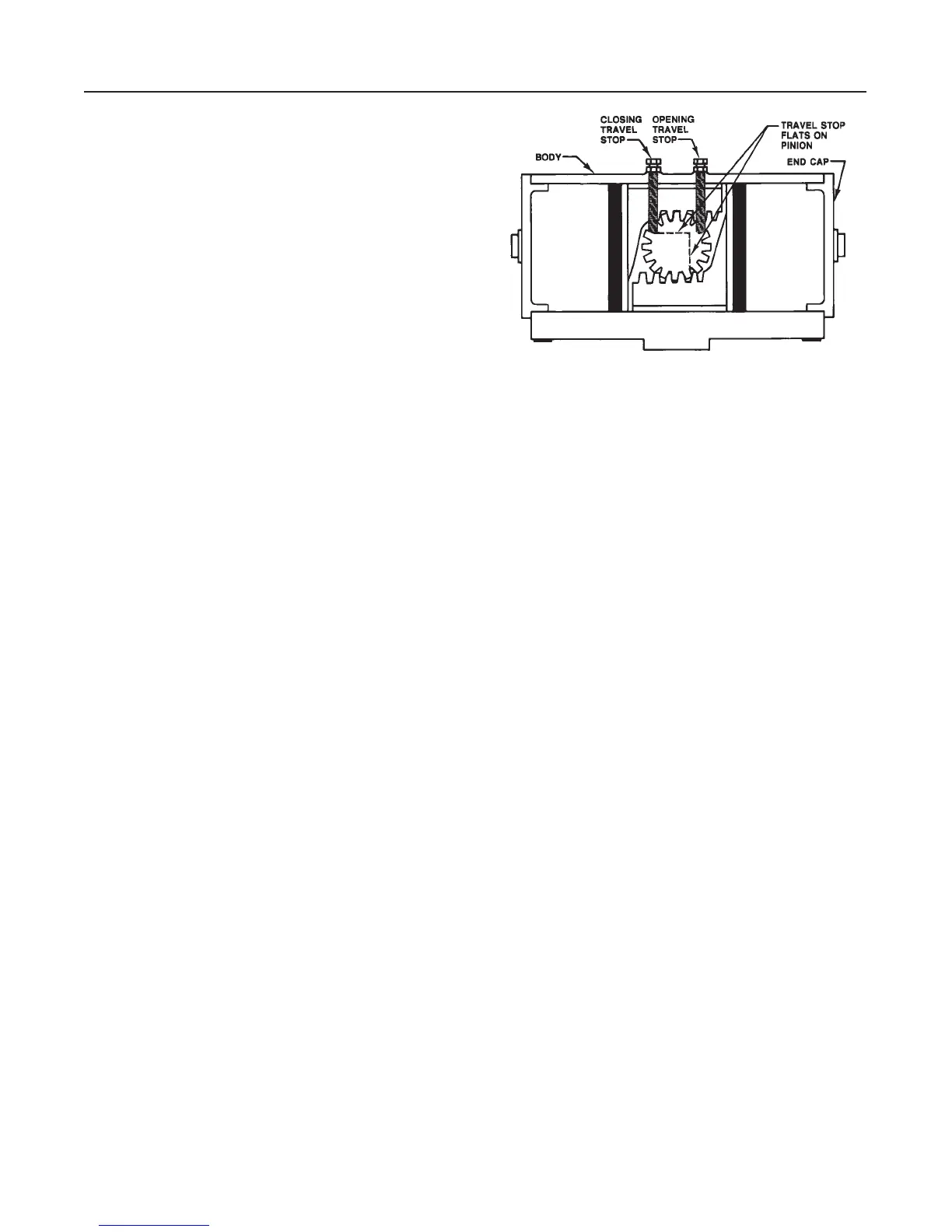
5. Rotate the pinion (key 2) so its travel stop flats are
properly oriented for correct actuator output rotation
and for correct valve rotation (see figure 8). The orien-
tation shown in figure 8 is correct for counterclockwise
output rotation of the actuator and clockwise to close
valves.
6. Push both pistons together until their racks are in
contact with the pinion (key 2). Rotate the pinion
clockwise to draw the pistons together.
Note
When the pistons are together and the
rack teeth are properly engaged by the
teeth on the pinion, the two travel stop
flats will each be at a right angle to an
axis of the body.
Installing the Travel Stops
Key numbers referenced in the following steps are
shown in figure 10 for double-acting actuators and in
figure 11 for spring-return actuators unless otherwise
indicated.
1. Thread the travel stop lock nuts (key 10) on the
travel stop bolts (key 9) if they were removed. Install
Figure 9. Travel Stop Installation for
Counterclockwise Output Rotation
A5835/ IL
the sealing washers (key 11) against the travel stop
lock nuts.
2. With the pistons together, screw in a travel stop
bolt (key 9) for the closing travel stop (see figure 9)
until the bolt just touches the travel stop flat on the
pinion. It may be necessary to move the travel stop
lock nut on the bolt to allow the bolt to touch the pin-
ion.
3. Rotate the pinion 90 to drive the pistons apart.
Make certain the rotation is only 90. Screw in a travel
stop bolt (key 9) for the opening travel stop (see figure
9) until the bolt just touches the travel stop flat on the
pinion. It may be necessary to move the travel stop
lock nut on the bolt to allow the bolt to touch the pin-
ion.
4. Make the final travel stop adjustments in accor-
dance with the Travel Stop Adjustments procedure in
the Installation section after the end caps are installed
and the actuator is mounted on the valve.
Installing the End Caps on Double-Acting
Actuators
Assemble and install the end caps as described be-
low. The actuator has two end caps. Perform these
same steps on both end caps. Key number locations
are shown in figure 10.
1. Apply a lithium-based grease to the end of the
body bore and to the surface of the end cap (key 4)
that fits into the body bore. Make certain the grease
gets into the grooves of the end cap.
2. Apply a light coat of lithium-based grease to the
end cap O-ring (key 13), and then install it in its
groove of the end cap (key 4). The O-ring groove is
the groove adjacent to the flange on the end cap.
3. Insert the end cap (key 4) into the body bore.