Instruction Manual Supplement
D103546X012
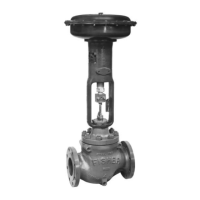
A41 Valve
June 2017
4
The A41 valve is intended to be part of final element subsystem as defined per IEC 61508 and the achieved SIL level of
the designed function must be verified by the designer.
Pressure, Temperature, and Environmental limits
The designer of a SIF must check that the product is rated for use within the expected environmental limits. Refer to
the A41 valve product bulletin for environmental limits.
Application limits
The materials of construction of A41 valves are specified in the product bulletin. A range of materials are available for
various applications. The serial card will indicate what the materials of construction are for a given valve. It is especially
important that the designer check for material compatibility considering onsite chemical contaminants and
environmental conditions. If the A41 valve is used outside of the application limits or with incompatible materials, the
reliability data provided becomes invalid.
Diagnostic Response Time
The A41 valve does not perform any automatic diagnostic functions by itself and therefore has no diagnostic response
times of its own. However, automatic diagnostics of the final control subsystem may be performed such as Partial
Valve Stroke Testing (PVST). This typically will exercise the valve over a small percentage of its normal travel without
adversely affecting the flow through the valve. If any failures of this PVST are automatically detected and annunciated,
the diagnostic response time will be the PVST interval time. The PVST must be performed 10 times more often than an
expected demand in order for credit to be given for this test. Typically this test could be performed monthly or weekly.
Design Verification
A detailed Failure Mode, Effects, and Diagnostics Analysis (FMEDA) report is available from Emerson. This report details
all failure rates and failure modes as well as the expected lifetime.
The achieved Safety Integrity Level (SIL) of an entire Safety Instrumented Function (SIF) design must be verified by the
designer via a calculation of PFD
AVG
considering architecture, proof test interval, proof test effectiveness, any
automatic diagnostics, average repair time and the specific failure rates of all products included in the SIF. Each
subsystem must be checked to assure compliance with minimum hardware fault tolerance (HFT) requirements.
When using A41 valves in a redundant configuration, a common cause factor of at least 5% should be included in the
Safety Integrity calculations. This value is dependent on the level of common cause training and maintenance in use at
the end user's facility.
The failure rate data listed the FMEDA report is only valid for the useful lifetime of A41 valves. The failure rates will
increase after this time period. Reliability calculations based on the data listed in the FMEDA report for mission times
beyond the useful lifetime may yield results that are too optimistic, i.e. the calculated Safety Integrity Level will not be
achieved.

 Loading...