Instruction Manual Supplement
D103546X012
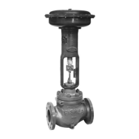
A41 Valve
June 2017
6
General Requirements
The system's response time shall be less than process safety time. The final control element subsystem needs to be
sized properly to assure that the response time is less than the required process safety time. The A41 valve will move
to its safe state in less than the required SIF's safety time (a typical value is 3 seconds) under the specified conditions.
All SIS components including the A41 valve must be operational before process startup.
The user shall verify that the A41 valve is suitable for use in safety applications.
Personnel performing maintenance and testing on the A41 valve shall be competent to do so.
Results from the proof tests shall be recorded and reviewed periodically.
The useful life of the A41 valve is discussed in the Failure Modes, Effects, and Diagnostic Analysis Report for the Fisher
A41 valve.
Installation and Commissioning
Installation
The Fisher A41 valve must be installed per standard practices outlined in the appropriate instruction manual.
The environment must be checked to verify that environmental conditions do not exceed the ratings.
The A41 valve must be accessible for physical inspection.
Physical Location and Placement
The Fisher A41 valve shall be accessible with sufficient room for the actuator, pneumatic connections, any other
components of the final control element. Provisions shall be made to allow for manual proof testing.
Pneumatic piping to the actuator shall be kept as short and straight as possible to minimize the airflow restrictions and
potential clogging. Long or kinked pneumatic tubes may also increase the valve closure time.
The A41 valve shall be mounted in a low vibration environment. If excessive vibration can be expected special
precautions shall be taken to ensure the integrity of pneumatic connectors or the vibration should be reduced using
appropriate damping mounts.

 Loading...