Type EZR
11
2. Back out the pilot adjusting screw(s).
3. For easy initial startup, set the restrictor to the “8”
position. For future startups, the restrictor can be
left in the desired run position.
4. SLOWLY OPEn the valves in the following order:
a. Pilot supply and control line valve(s), if used
b. Inlet block valve
c. Outlet block valve
5.
For a 161 Series pilot with Type 112 restrictor,
turn the restrictor(s) to position “2” or to the desired
run position. For a PRX Series pilot, turn the
restrictor screw 1 turn counterclockwise from
fully seated (turn restrictor fully clockwise then 1
turn counterclockwise) and the damper screw
fully counterclockwise.
6.
set the pilot to the
desired outlet (control) pressure according to the
pilot adjustment procedure
.
adjust the upstream working
pilot until intermediate pressure is higher than
the desired setpoint of the monitor pilot. Adjust
the downstream monitoring pilot to the desired
monitoring takeover pressure. Reduce the
upstream pilot to the normal outlet pressure setting.
adjust the downstream working pilot to a setpoint
higher than the setpoint of the monitor pilot.
Adjust the upstream monitoring pilot to the desired
monitor takeover pressure. Reduce the downstream
pilot setting to normal outlet pressure setting.
adjust the
setpoint of the upstream monitor pilot to the desired
maximum pressure. Adjust the upstream working
pilot to the desired intermediate pressure setting.
Adjust the downstream pilot to a pressure setting
slightly above the upstream monitor pilot pressure
setting. Adjust the upstream monitor pilot to its
desired setpoint. The setpoint of the monitor pilot
should be adjusted at least to the guidelines shown
in Table 9. The maximum may be greater. Then,
establish nal desired downstream pressure by
adjusting the downstream working regulator pilot.
remove the pilot closing cap
(key 16, Figure 19 or key 22, Figure 20) and, on
161EB Series only, loosen the locknut (key 12,
Figure 19). Turn the adjusting screw (key 11,
Figure 19 or key 35, Figure 20) into the spring case
(key 2, Figure 19 or key 3, Figure 20) to increase the
downstream pressure. Turn the adjusting screw out of
the spring case to decrease the downstream pressure.
loosen locknut
(key 2) and turn the adjusting screw into the spring case
to increase (or out of the spring case to decrease) the
downstream pressure. When the required downstream
pressure is maintained for several minutes, tighten the
locknut to lock the adjusting screw in position
and replace the pilot closing cap.
The Restrictor and Damper screws on the PRX Series
pilot control the regulator’s proportional band (droop)
and speed of response. Table 7 includes the appropriate
settings for low ow operation. For additional tuning
follow the steps outlined below:
1. Start with the restrictor screw 1 turn
counterclockwise from fully seated (turn restrictor
fully clockwise then 1 turn counterclockwise) and
the damper screw fully counterclockwise.
2. Turn damper screw clockwise until desired
performance is achieved. This reduces the ow
path of the damper. If the damper becomes fully
seated (no longer able to turn clockwise) and the
desired performance has not been achieved, return
the damper screw to the fully counterclockwise position.
!
WARnInG
3. Turn the restrictor screw an additional turn
counterclockwise from fully seated. This increases
the ow path of the restrictor. If additional tuning
is required, repeat step 2. Follow this method until
desired performance is achieved.
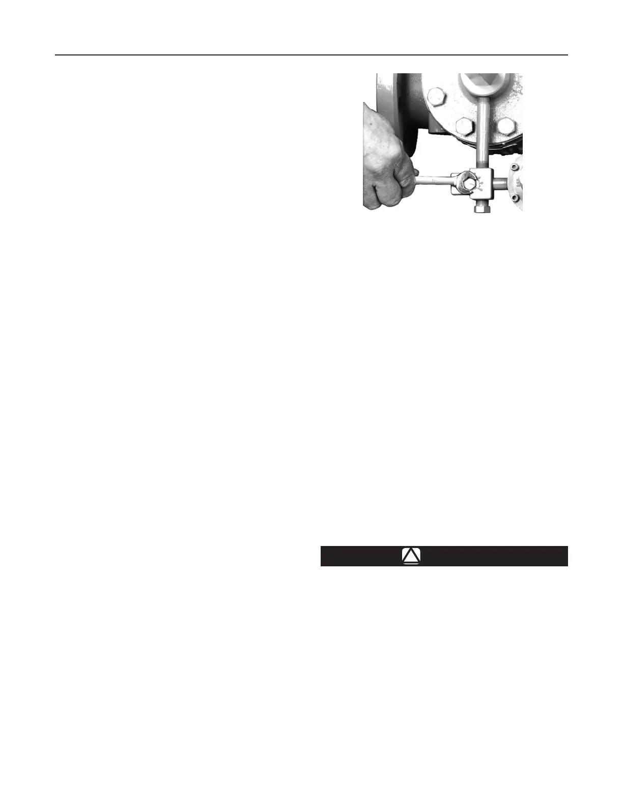
The Type 112 restrictor controls the regulator’s
proportional band (droop) and speed of response. The
restrictor can be used to ne tune the regulator for
Figure 6. Restrictor Adjustment
W4559_1

 Loading...


