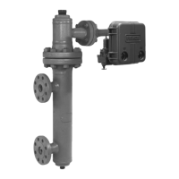
Type EZR
19
• Washer (key 79 for NPS 6 (DN 150) size only)
• Main Spring (key 12), small end rst
• Upper Spring Seat (key 17), make sure to place
the large end toward the spring
• First Back-up Ring (key 16)
• O-ring (key 18)
• Second Back-up Ring (key 16)
• Indicator Fitting (key 19), the back-up rings (key 16)
and O-ring (key 18) should slide into the indicator
tting and the small end of the upper spring seat
(key 17) should slide into the indicator tting.
• First Hex Nut (key 4)
• Indicator Washer (key 20)
• Second Hex Nut (key 4)
11. Install the indicator tting (key 19) into the bonnet
(key 2, Figure 14), tighten to the proper torque
(see Table 13).
To set the travel indicator, hold the indicator
cover (key 21) next to the indicator tting
(key 19). Screw the hex nuts (key 4) and the
indicator washer (key 20) down on the indicator
stem (key 15) until the washer is even with
the lowest marking on the indicator cover.
Lightly lubricate the indicator cover threads and
install. Replace the indicator protector (key 22).
place the main spring
(key 12) into the bonnet. Install the indicator plug
(key 19) and tighten to proper torque (see Table 13).
Trim Parts
1. As shown in Figure 11, remove the body plug
(key 3) to let the plug spring (key 6), and valve
plug (key 4) drop freely from the body.
2. Inspect the removed parts and body plug O-ring
(key 15), replace as necessary, and make sure the
plug seating surfaces are free from debris.
3. Sparingly apply lubricant to the body plug O-ring
(key 15) and the threads of the body plug (key 3).
Install the body plug O-ring over the body plug.
4. Stack the plug spring (key 6), and valve plug
(key 4) on the body plug (key 3). Install the body
plug with stacked parts into the body (key 1).
1 or 1-1/4 x 1 (25 or 32 x 25) 75 to 95 (102 to 129) 4 to 6 (5,4 to 8,1) 90 to 160 (122 to 217) 90 to 160 (122 to 217)
2 x 1 or 2 (50 x 25 or 50) 55 to 70 (75 to 95) 6 to 8 (8,1 to 11) 90 to 160 (122 to 217) 90 to 160 (122 to 217)
3 (80) 100 to 130 (136 to 176) 19 to 25 (26 to 34) 200 to 300 (271 to 407) 200 to 300 (271 to 407)
4, 6 x 4, or 8 x 4
(100, 150 x 100, or 200 x 100)
160 to 210 (217 to 285) 19 to 25 (26 to 34) 200 to 300 (271 to 407) 200 to 300 (271 to 407)
6, 8 x 6, or 12 x 6
(150, 200 x 150, or 300 x 150)
275 to 300 (373 to 407) 50 to 100 (68 to 136) 300 to 425 (407 to 577) 300 to 425 (407 to 577)
8 (200) 400 to 450 (542 to 610) 90 to 110 (122 to 149) 300 to 425 (407 to 577) 300 to 425 (407 to 577)
Table 13. Torque Values
Figure 10. Travel Indicator Parts
HEx nUTS
UPPER SPRInG
RInGS
W7400_1
 Loading...
