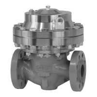
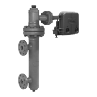
Type EZR
17
For NPS 2 x 1 (DN 50 x 25) sizes, the lower
adaptor (key 132) must be assembled on the
cage before placing in the body. Lightly lubricate
the lower adaptor O-rings (keys 121 and 67) and
place the lower adaptor on a at surface. Then
press the cage down into the lower adaptor.
5. Lubricate the top and bottom of the outer
edge (bead area) of the diaphragm and place
diaphragm and plug assembly (key 9) on the
cage (key 7). For NPS 2 x 1 (DN 50 x 25) sizes,
the upper adaptor (key 131) must be placed on
the cage before the bonnet (key 2). Lightly
lubricate the upper adaptor O-ring (key 133) and
then press the upper adaptor onto the cage.
6. If travel indicator was removed, lightly lubricate
the travel indicator assembly threads and screw
it into the bonnet (key 2). See Travel Indicator
Assembly Maintenance for maintenance.
7. Install the bonnet (key 2) in proper orientation.
cAUTIOn
®
8. Lubricate cap screws (key 3) and secure the
bonnet (key 2), using an even crisscross pattern.
It may be necessary to push down on bonnet to
start cap screws. Tighten cap screws to proper
torque (see Table 13).
The diaphragm and plug assembly can be replaced
as a single unit (a diaphragm cartridge), or
individual components within the assembly can be
replaced. When replacing individual components,
inspect each component for damage and wear,
and replace parts as needed. Key numbers for the
following assembly and disassembly procedure are
referenced in Figures 9 and 14.
1. Place a screwdriver or similar tool through the
hole in the top plug (key 5).
Outlet pressure suddenly rises above
setpoint and approaches inlet pressure
• If travel indicator is in UP position, check restrictor and pilot supply lter for plugging
• If travel indicator is in DOWN position, check main valve for debris or diaphragm damage
Outlet pressure normal at low ow but
falls below setpoint at high ow
• Check main valve inlet strainer for plugging
• Check inlet pressure at high ow condition
• Check sizing calculations to be sure main valve body is large enough for load
• Check for undersized or restricted control line (use the minimum size given in step 6 of All Installations of the
Type EZR Installation section).
• Adjust restrictor to a lower setting
Outlet pressure cycles
• Adjust restrictor to a higher setting
• Check control line placement. Make sure it is not located in a turbulent area.
• Make sure there is not a restriction in the control line, such as a needle valve.
Gas escapes from pilot spring case • Replace pilot diaphragm assembly
Gas escapes from travel indicator • Replace indicator stem O-ring, if indicator is not desired, convert to a non-travel indicator assembly
Regulator unexpectedly closes or falls
below setpoint
• Check pilot for ice. Moisture in the gas can cause ice to form and build up in the pilot, blocking the ow.
This most commonly occurs when ambient temperature is 30° to 40°F (-1° to 4°C). Heating the regulator or
adding a de-icing agent will reduce the possibility of icing.
Outlet pressure approaches inlet
pressure when no ow is desired
• Check main valve O-rings for damage or improper installation
• Check cage and diaphragm surfaces for erosion or trapped debris
• Check pilot valve plug and seat for seating surface damage or debris
• Check pilot for ice
Regulator will not open
• Check for clogged control line
• Make sure control line is installed and open
• Check for damage to the main valve diaphragm
• On new installations, make sure the control line and pilot supply are properly connected
Regulator will not close
• Make sure the pilot supply is properly connected
• Check restrictor for clogging
• Check the main valve diaphragm for damage
• Check for a broken control line
High lock-up pressure with slow shutdown • Check for debris on main valve or pilot seat
High lock-up pressure with fast shutdown • Adjust restrictor to a higher setting
Note: If you were unable to solve your problem using this troubleshooting guide, contact your local Sales Ofce.
Table 12. Troubleshooting Guide
 Loading...
