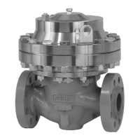
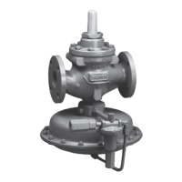
Type EZR
10
Connect the “A” port of upstream
Type
PRX-125 pilot
downstream of both regulators.
The pilot supply pressure connection for the
downstream Type EZR regulator must be directly
upstream of the Type EZR using intermediate pressure
and connected to the “S” port of the downstream
Type PRX-120. Install a Type 252 pilot supply lter
upstream of the pilot, if needed, to keep the supply
source from clogging the restrictor in the pilot. Inspect
and clean this lter regularly to make sure it has not
been plugged. Connect the loading port (Port L) of
the downstream Type PRX-120 pilot to the bonnet of
the downstream Type EZR regulator. Connect the “A”
and “B” ports of the downstream Type PRX-120 pilot to
downstream pressure.
Signicant restrictions in control lines can prevent
proper pressure registration. Connect the control line
a minimum of 8 to 10 pipe diameters downstream of
the regulator in a straight run of pipe. Do not make
the control line connection in a turbulent area, such as
in or directly downstream of a swage or elbow. When
used, a hand valve should be a full ow valve such as
full port ball valve.
Table 4 shows the minimum differential pressure
requirements across an individual regulator. Because
this application uses a rst-stage and second-stage
pressure reduction, add the minimum differential
pressure for each regulator together to establish the
required pressure drop across the station. Do not
exceed maximum pilot ratings given in Table 3.
cAUTIOn
1. Make sure all block and vent valves are closed.
Figure 5. Type EZR-PRX-PRX Working Monitor Schematic
InLET
FILTER
PILOT
(nO RESTRIcTOR ScREW)
S
S
L
L
A
FILTER
S
L
A
OUTLET
PILOT
A
InLET PRESSURE
OUTLET PRESSURE
M1001
 Loading...
