Instruction Manual
D103198X012
i2P-100 Transducer
July 2014
11
Mounting
When a transducer is ordered as part of a control valve assembly, the factory mounts the transducer on the actuator
and connects the necessary tubing, then adjusts the transducer as specified on the order. See figures 3 and 4 for
typical mounting configurations.
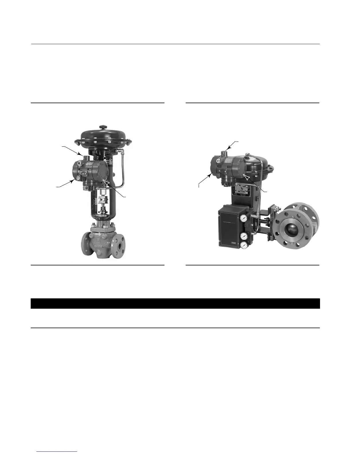
Figure 3. Fisher i2P‐100 Electro‐Pneumatic
Transducer Mounted on a Size 30 667 Sliding‐Stem
Actuator
W8723
CONDUIT
CONNECTION
FIELD
TERMINATION AND
ELECTRONICS
MODULE CAP
CONVERTER
MODULE CAP
Figure 4. Fisher i2P‐100 Electro‐Pneumatic
Transducer Mounted on a Size 33 1052 Rotary
Actuator with 3610J Positioner and V300B Rotary
Valve
W8693
CONDUIT
CONNECTION
FIELD TERMINATION
AND ELECTRONICS
MODULE CAP
CONVERTER
MODULE CAP
Transducers also can be ordered separately for mounting on a control valve assembly already in service, or for
mounting on a 2 inch diameter pipestand, or a flat surface. The transducer may be ordered either with or without
mounting parts.
CAUTION
Do not mount the vent in a downward position as the vent will not drain properly and may become blocked with ice or
debris, resulting in process instability.
Mounting parts include a mounting plate and bolts and, if ordered for pipestand mounting, a pipe clamp. Tubing is not
included if the transducer is not factory mounted. Use 3/8‐inch diameter tubing for all input and output connections.
The length of tubing between the transducer output and the final control element should be as short as possible.
Transducer overall dimensions are shown in figure 5. If weatherproofing is required, mount the transducer so that the
vent can drain. Do not allow moisture or condensate to collect in the vent.
Pneumatic Connections
As shown in figure 5, all pressure connections on the transducer are 1/4 NPT internal connections. Use 3/8‐inch tubing
for all pressure connections. Refer to the vent subsection below for remote vent connections.

 Loading...