Instruction Manual
D103198X012
i2P-100 Transducer
July 2014
16
For intrinsically safe areas, current monitoring during operation must be with a meter approved for use in hazardous areas.
Equipment Required
Choose a current or voltage source that is capable, without switching ranges, of driving the transducer through its
entire input range. Switching ranges on a current or voltage source will produce spikes or mid‐scale reverses in the
input signal presented to the transducer, causing errors. The current source should be capable of delivering 30 mA
with 30 VDC maximum compliance voltage.
Calibration Procedure
WARNING
To avoid personal injury or property damage due to an uncontrolled process provide some temporary means of process
control before beginning the calibration procedure.
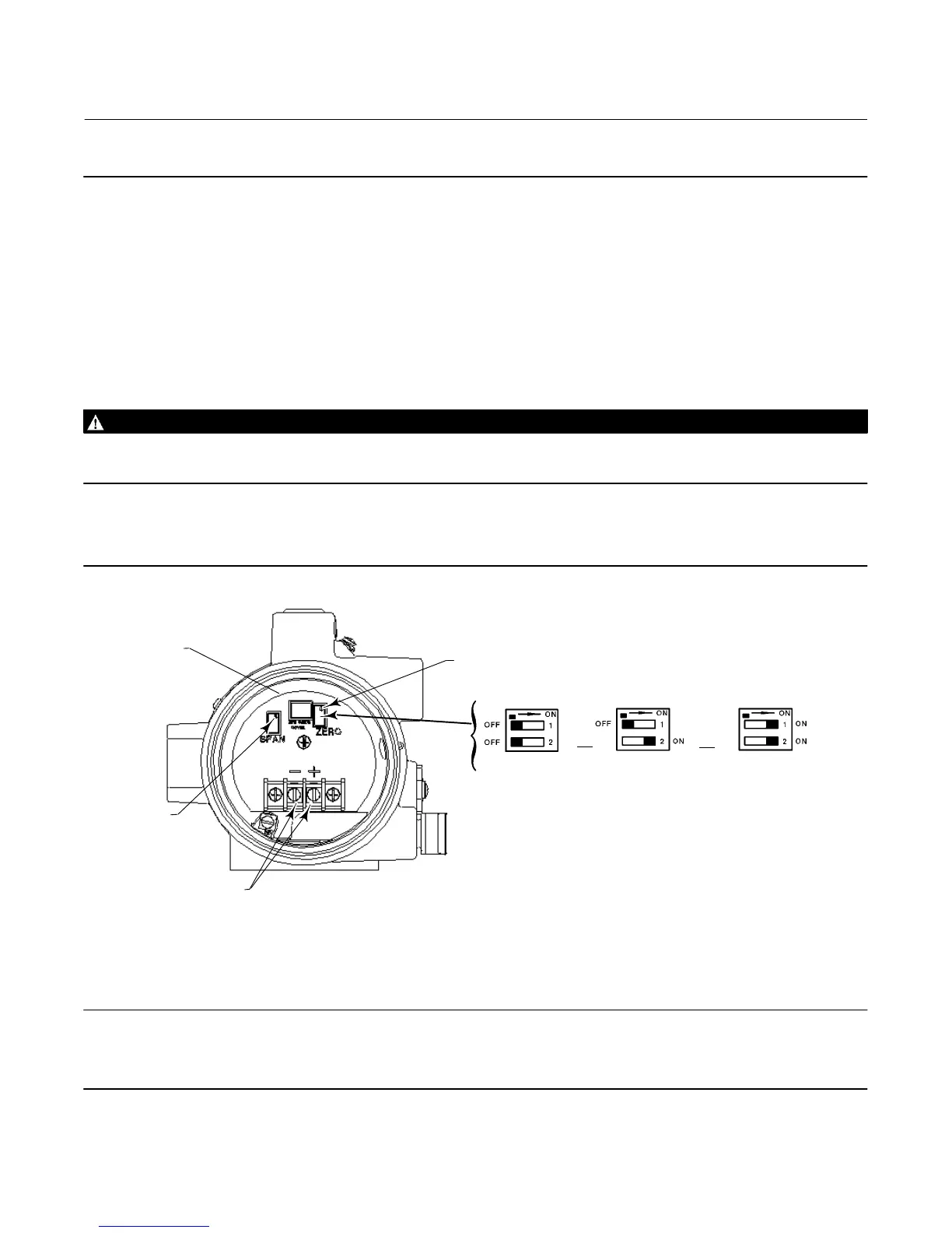
Refer to figure 10 for adjustment locations.
Figure 10. Zero and Span Adjustments and Switch Settings
PCB/CUP
ASSEMBLY
SPAN
ADJUSTMENT
FIELD WIRING
CONNECTION
SWITCH SETTINGS
(3)
ZERO
ADJUSTMENT
4‐20 mA3‐15 psi
4‐12 mA3‐15 psi
OR
4‐20 mA6‐30 psi
OR
4‐20 mA2‐33 psi
12‐20 mA3‐15 psi
{
- +
GE03345
OR
OR
NOTES:
THE SWITCH SETTINGS WILL PRODUCE THE PERFORMANCE CHARACTERISTICS AS INDICATED. FOR
EXAMPLE, BOTH SWITCHES PLACED IN THE OFF POSITION WILL CREATE A 4‐20 mA INPUT WITH A
3‐15 PSIG OUTPUT PERFORMANCE CHARACTERISTIC
1. INPUT SIGNAL SPLIT RANGE IS SELECTABLE VIA DIP‐SWITCH CONFIGURATION.
2. OUTPUT RANGE DIP‐SWITCH SELECTION FOR 0.14 TO 2.0 BAR (2 TO 33 PSIG) USES SETTING B
AND REQUIRES ZERO TO SPAN ADJUSTMENTS. FOR OTHER RANGES, ZERO AND SPAN ADJUST
MENTS NEEDED.
3. SWITCH 1 SET TO THE ON POSITION AND SWITCH 2 SET TO THE OFF POSITION IS NOT A VALID
SWITCH SETTING.
SETTING A
SETTING B
(1,2)
SETTING C
(1)
Note
The following steps are for a 4‐20 mA, 0.2 to 1.0 bar (3 to 15 psig) configured unit. The same procedure is used for other
configurations.

 Loading...