Instruction Manual
D103198X012
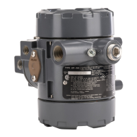
i2P-100 Transducer
July 2014
2
CAUTION
Dropping or rough handling of the transducer can cause damage to the converter module resulting in a shifted output or a
minimum output.
Description
The transducer receives a 4‐20 mA DC input signal and transmits a proportional user field‐configurable pneumatic
output pressure to a final control element. The pneumatic output range are typically 0.2 to 1.0 bar (3 to 15 psig), 0.4
to 2.0 bar (6 to 30 psig), and 0.14 to 2.3 bar (2 to 33 psi). A typical application is in electronic control loops where the
final control element is a control valve assembly that is pneumatically operated. The input signal and output pressure
range of the transducer is indicated on the nameplate, attached to the housing.
Specifications
Specifications for the i2P‐100 transducer are listed in table 1.
WARNING
This product is intended for a specific current range, temperature range and other application specifications. Applying
different current, temperature and other service conditions could result in malfunction of the product, property damage or
personal injury.
Educational Services
For information on available courses for the i2P‐100 electro‐pneumatic transducer, as well as a variety of other
products, contact:
Emerson Process Management
Educational Services, Registration
Phone: +1-641-754-3771 or +1-800-338-8158
e‐mail: education@emerson.com
http://www.emersonprocess.com/education

 Loading...