Instruction Manual
D103198X012
i2P-100 Transducer
July 2014
3
Table 1. Specifications
Input Signal
Available as standard with 4‐20 mA.
User configurable by dip switch for split ranging, see
table below.
Output Signal
(1)
Available as standard 0.2 to 1.0 bar (3 to 15 psig), 0.4
to 2.0 bar (6 to 30 psig), or 0.14 to 2.3 bar
(2 to 33 psig). User configurable by dip switch
selection and zero and span potentiometer
adjustment, see table below.
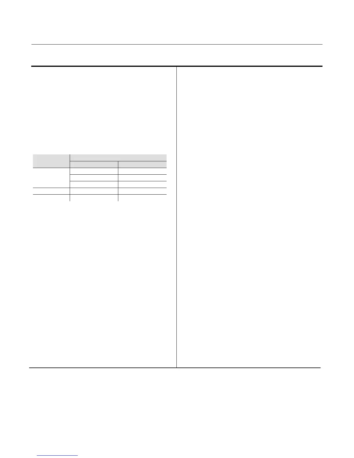
Input Signal
Output Pressure
Bar psig
4‐20 mA DC
0.2 to 1.0 3 to 15
0.4 to 2.0 6 to 30
0.14 to 2.3 2 to 33
4‐12 mA DC 0.2 to 1.0 3 to 15
12‐20 mA DC 0.2 to 1.0 3 to 15
Equivalent Circuit
The i2P‐100 equivalent circuit is a series circuit
consisting of a constant voltage drop (battery) of
approximately 4 VDC and a total resistance of 40
ohms. Input is shunted by two 6.8 V zener diodes (see
figure 9).
Supply Pressure
(2)
Recommended: 0.3 bar (5 psi) higher than upper
range limit of output signal
Maximum: 3.4 bar (50 psig)
Medium: Air or Natural Gas
Maximum Steady-State Flow Rate
Refer to tables 3 and 4
Maximum Output Air Capacity
(3)
8.0 m
3
/hr (300 scfh) at 1.4 bar (20 psig) supply
pressure
Performance
(4)
Reference Accuracy: ±1.0% of full scale output span;
includes combined effects of hysteresis, linearity, and
deadband
Independent Linearity: ±0.5% of full scale output span
Hysteresis: 0.4% of full scale output span
Frequency Response: Gain is attenuated 3 dB at 3 Hz
with transducer output signal piped to a typical
instrument input
Temperature Effect: ±0.14% per degrees Celsius
(±0.075% per degrees Fahrenheit) of span
Supply Pressure Effect: 0.2% of full scale output span
per psi supply pressure change
Vibration Effect: Less than 1% of full scale output span
when tested to ISA S75.13
Electromagnetic Compatibility
Meets EN 61326‐1 (First Edition)
Immunity—Industrial locations per Table 2 of
EN 61326‐1 Standard. Performance is shown
in table 2 below.
Emissions—Class A
ISM equipment rating: Group 1, Class A
Operating Ambient Temperature Limits
(2)
-40 to 85_C (-40 to 185_F)
Electrical Seal
Single sealed device per ANSI/ISA 12.27.01
Electrical Classification
Hazardous Area:
CSA—Intrinsically Safe, Explosion-proof,
Type n, Dust‐Ignition proof
FM—Intrinsically Safe, Explosion-proof,
Type n, Non‐incendive, Dust‐Ignition proof
ATEX—Intrinsically Safe, Flameproof, Type n
IECEx—Intrinsically Safe, Flameproof, Type n
Refer to Hazardous Area Classifications and Special
Instructions for “Safe Use” and Installation in
Hazardous Locations, starting on page 7, for specific
approval information
(continued)

 Loading...