Instruction Manual
D102178X012
V260 Valve
July 2017
3
Installation
WARNING
D To avoid personal injury, always wear protective gloves, clothing, and eyewear when performing any installation
operations.
D To avoid personal injury or property damage resulting from the bursting of pressure retaining parts, be certain the
service conditions do not exceed the limits given in this manual.
D To avoid personal injury or property damage that can result from the sudden release of process pressure if valve or
mating pipe flange pressure ratings are exceeded, provide a relief valve for over‐pressure protection as required by
government or accepted industry codes and good engineering practices.
D Service conditions are limited for valve and trim material combinations. Do not apply any other service condition to the
valve without first contacting your Emerson sales office
or Local Business Partner.
D Personal injury could result from packing leakage. The valve packing was tightened before shipment however, the
packing might require some readjustment to meet specific service conditions.
D Check with your process or safety engineer for any additional measures that must be taken to protect against process
media.
D If installing into an existing application, also refer to the WARNING at the beginning of the Maintenance section in this
instruction manual.
D To avoid personal injury or property damage, a minimum of two swivel hoists must be used when lifting NPS 24 CL600
assemblies.
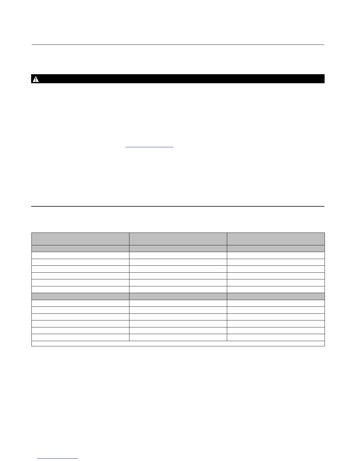
Table 2. Face‐to‐Face Dimensions and Approximate Weights
VALVE SIZE, NPS
(CL600
(1)
)
FACE‐TO‐FACE
DIMENSIONS
APPROXIMATE WEIGHT
mm kg
8 661 424
10 788 653
12 840 882
16 990.6 2472
20 1144 4313
24 1397 7257
Inches Pounds
8 26.04 975
10 31.04 1550
12 33.07 2025
16 39.0 5450
20 47.0 9500
24 55.0 16000
1. For CL150 and CL300 valves, face‐to‐face dimensions are the same as CL600 valves.
Key number locations are shown in figure 6, unless otherwise noted.
1. Install a three‐valve bypass around the control valve assembly if continuous operation will be necessary during
inspection and maintenance of the valve.
2. The valve is normally shipped as part of a control valve assembly, with an actuator mounted on the valve. The
valve/actuator assembly is adjusted at the factory before the unit is shipped.
If the valve or actuator has been purchased separately or if the actuator has been removed, mount the actuator
according to the Actuator Mounting section and the appropriate actuator instruction manual. Make any necessary
adjustments on the bench before installing the valve in the pipeline. With the valve in the pipeline, you cannot see the
exact position of the ball to determine the fully open or closed positions.