Instruction Manual
D102178X012
V260 Valve
July 2017
4
3. Standard flow direction is shown in figure 6. If possible, install the valve in a horizontal pipeline with the drive shaft
horizontal. The actuator can be right‐ or left‐hand mounted in any of the positions shown in the actuator instruction
manual. If necessary, refer to the appropriate actuator instruction manual for installation and adjustment
procedures.
4. Be certain the valve and adjacent pipelines are free of any foreign material that could damage the valve sealing
surfaces. Impurities or entrained solids in the process fluid could plug the passages in the trim. If the process fluid is
not clean, install a filter upstream to keep the pipeline free of impurities or entrained solids.
5. Provide appropriate flange gaskets, and place the valve in the pipeline. Tighten flange bolting in a criss‐cross
sequence to ensure the flange gaskets are loaded evenly.
Note
Standard Fisher V260 valve packings (key 105) are composed of:
D
Conductive packing ring (graphite ribbon packing), or
D
Partially conductive packing rings (For example: a carbon‐filled PTFE female adaptor with PTFE V‐ring packing or a
graphite‐composition packing ring with PTFE/composition packing ring)
In order to electrically bond the drive shaft to the valve body for hazardous area service, an alternate shaft‐to‐body bonding strap
can be provided by using the following step.
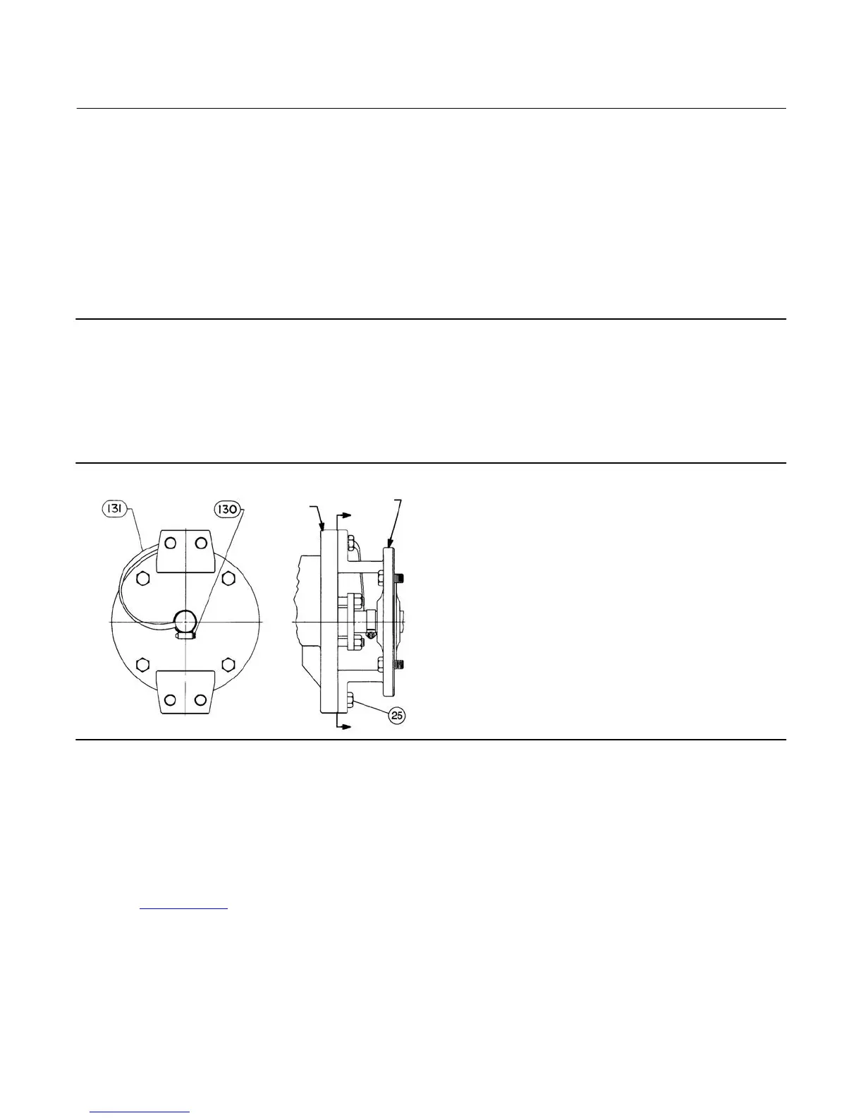
Figure 2. Optional Shaft‐to‐Body Bonding Strap Assembly
VALVE BODY
ACTUATOR
A
A
VIEW A-A
37A6528-A
A3143-2
6. For hazardous applications, attach the optional bonding strap assembly (key 131) to the valve drive shaft (key 6)
with the clamp (key 130) and connect the other end of the bonding strap assembly to the valve body with the
mounting cap screw as shown in figure 2.
7. Connect pressure lines to the actuator as indicated in the actuator instruction manual. When an auxiliary manual
actuator is used with a power actuator, install a bypass valve on the power actuator (if one is not supplied) for use
during manual operation.
8. If the valve has ENVIRO‐SEAL™ live‐loaded packing installed, an initial re‐adjustment may not be required,
depending on your application. See the Fisher instruction manual titled ENVIRO‐SEAL Packing System for Rotary
Valves (D101643X012
) for packing instructions and adjustments (see figure 3).
Maintenance
Valve parts are subject to normal wear and must be inspected and replaced as necessary. The frequency of inspection
and replacement depends upon the severity of service conditions.