Instruction Manual
D102178X012
V260 Valve
July 2017
6
Replacing Packing
Replacing the packing requires bleeding off the system and removing the actuator from the valve. Valve/actuator
adjustments cannot be made correctly without observing the fully open or closed position of the ball (key 11). It is not
necessary to remove the valve from the pipeline, if care is taken to note the position and alignment of the lever and
shaft and to not disturb the turnbuckle position.
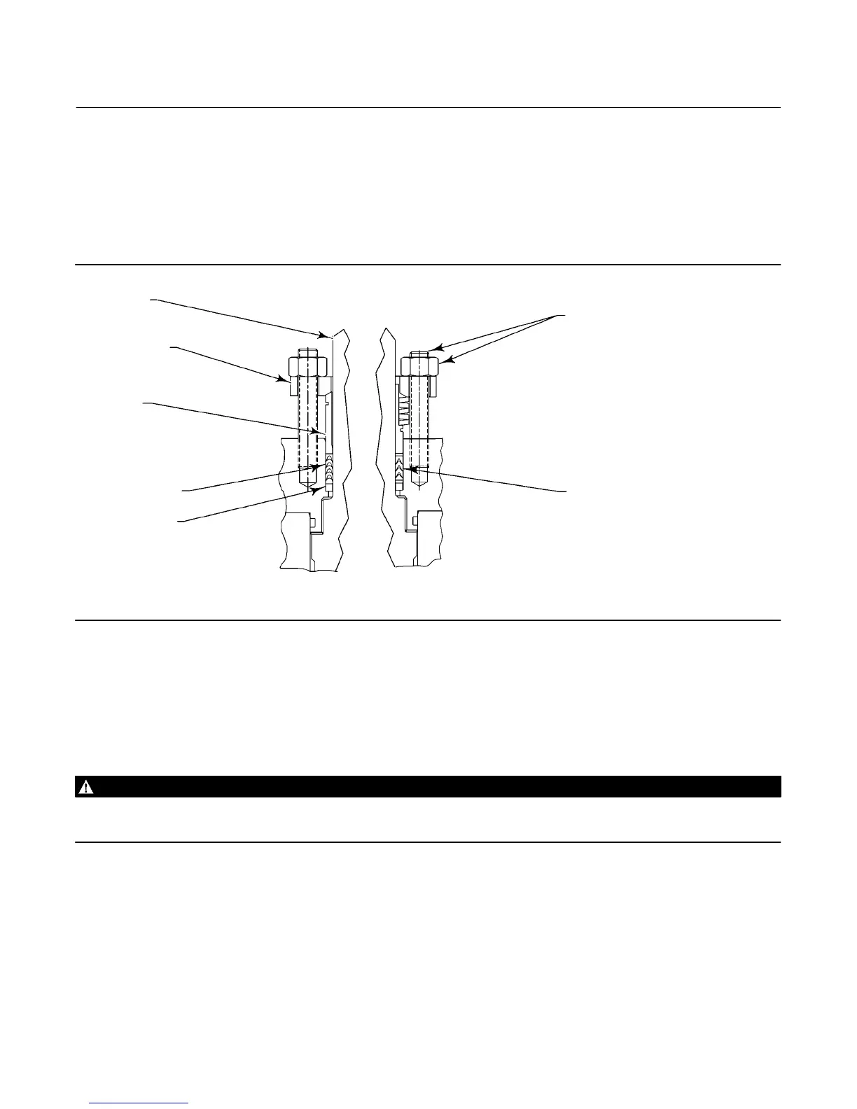
Figure 3. Packing Arrangement Details
STANDARD
PACKING ARRANGEMENT
ENVIRO-SEAL
PACKING ARRANGEMENT
DRIVE SHAFT
(KEY 20)
PACKING FLANGE
(KEY 102)
PACKING
FOLLOWER
(KEY 114)
TYPICAL PTFE
V-RING PACKING
SET (KEY 105)
PACKING BOX
RING (KEY 107)
PACKING STUD
AND NUT
(KEYS 100 AND 101)
TYPICAL
ENVIRO-SEAL
PTFE V-RING
PACKING SET
94BA02200-D
B2472-1
Disassembly
1. Isolate the control valve from the line pressure, release pressure from both sides of the valve body, and drain the
process media from both sides of the valve. If using a power actuator, shut off all pressure lines (or other power
source) to the power actuator, release pressure from the actuator, and disconnect the pressure lines from the
actuator. Use lock‐out procedures to be sure that the above measures stay in effect while you work on the
equipment.
WARNING
See the WARNING at the beginning of the Maintenance section for more information before removing the valve from the
pipeline.
2. Remove line bolting, remove the control valve from the pipeline, and place the actuator/valve assembly on a flat
surface.
3. Remove the actuator cover. Note and mark the orientation of the actuator with respect to the valve body and the
lever orientation with respect to the valve drive shaft, to assist with reassembly.
4. Loosen the lever locking device cap screw. Loosening the lever turnbuckle adjustment is not necessary during
disassembly. When remounting the actuator, the turnbuckle will be used for actuator adjustments.
5. Removing the actuator from the valve: