13
MAINTENANCE
Maintenance of your FLETCHER 2200 PROFESSIONAL MAT CUTTER is mostly a matter of cleanliness.
1. Keep a dry, lint free cloth near the machine. Wipe the Shaft and Mat Clamp daily and frequently during use to
remove loose paper particles, dust, and other foreign matter. DO NOT USE OIL OR WAX. Cover the machine with a
dust cover when not in use.
2. Periodically check the squareness and accuracy of sizing cuts, Mat Guide squareness and dimensions of mat bor-
ders. If corrections are required, follow the procedures outlined in the ADJUSTMENTS section. The frequency of
inspection depends upon how many people are using the cutter and the care it is given. If set up properly and the
mounting and adjustment screws are not changed, it will produce excellent results indefinitely.
3. If the Cutting Head makes a rumbling noise it is caused by paper debris on the Mat Clamp or Ball Bearings.
First, wipe the top of the Mat Clamp thoroughly. Slightly loosen the set screw (L) shown on the previous page in
Figure 20. Tack down one end of a 6" strip of tape on the top of the Mat Clamp in the path of the Roller Bearing and
fold the tape back away from the Cutting Head so the glue side of the tape is facing up. Slowly slide the Cutting
Head over the tape. Debris will be transferred to the tape which can be discarded. Repeat this procedure for the other
Ball Bearing track. Be sure to re-adjust the set screw (L) as described on the prior page.
4. Both the bevel and straight pivot heads on the Cutting Head should rotate freely, but without excessive play. The
Pivot Screw, accessible after removing the Magazines, must be tight. Shim Washers are available in four different
thicknesses from .002” to .006” (.051mm to .152mm). Choose a combination of shims and insert the Pivot Screw
through them before tightening. These washers are identified as Ref. number 5 in the Cutting Head Parts List.
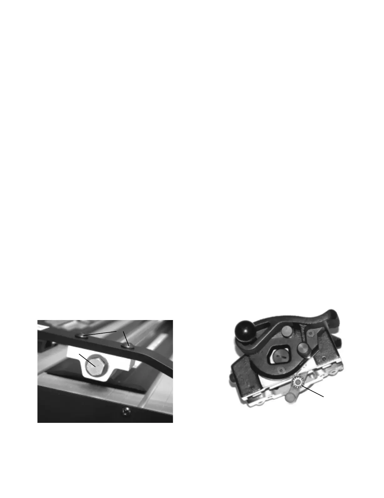
5. If it is ever necessary to remove the Cutting Head, follow this procedure:
a. Remove both blade Magazines. Remove the hex head bolt (A) from the lower end of the Shaft. Be sure to keep
the spring washer with the bolt. See Figure 21.
b. Remove the two button head hex screws (B) from the lower Hinge Bracket using the hex wrench provided.
c. Slip the Shaft Bracket off the Shaft. Lift the Clamp Handle just enough to allow the Shaft Bracket to be
removed.
d. Slide the Cutting Head off the shaft. Do not lift the Clamp Handle any higher than clearance requires. Hold your
hand beneath the Cutting Head to prevent the Ball Bearing (C) from falling to the floor. Re-assemble the
Cutting Head in the reverse order.
A
B
C
Figure 21
Figure 22
60
ABERTURA SIMPLE
El requisito más importante para cortar passe-partout es una cuchilla afilada. El passe-partout es un producto abrasivo
e irá gastando la cuchilla. El valor de passe-partout bien cortado es mucho mayor que el coste de una cuchilla.
1. Prepare una hoja de aprox. 8" (200 mm) de ancho y 40" (1.016 mm) de largo
y colóquela debajo del Gancho (A). Use un trozo de passe-partout
del mismo espesor que el que cortará y colóquelo sobre la hoja. Presione
sobre el Asa suavemente para sostener el passe-partout en su lugar. Deslice
el Cabezal de corte (B) sobre el borde del passe-partout y
haga girar el Pivote para insertar la cuchilla sobre la hoja. Ahora, puede
observar la punta de la cuchilla dentro del 1/3 del espesor de la hoja. Passe-
partout de distintos espesores exigen volver a probar y ajustar la extensión
de la cuchilla. Si presiona sobre el Asa con demasiada fuerza,
el Gancho se inclinará hacia arriba en el centro. Esto aumentará la distancia
entre la punta de la cuchilla y el passe-partout en el medio
del corte y la cuchilla no podrá penetrar totalmente cuando se corte un
passe-partout grande. Utilice sólo la presión suficiente como para trabar
el passe-partout en su lugar y evitar que se mueva. Vea la Figura 5.
2. El Gancho de ubicación (C) brinda ajustes establecidos, exactos y repetibles para los bordes del passe-partout desde
1-1/2" a 8" con aumentos de 1/2" para el sistema inglés. El Medidor de passe-partout agrega 1/8",
3/16", 1/4" ó 5/16 a las posiciones del Gancho de ubicación. El Gancho de ubicación tiene orificios para
los bordes del passe-partout que van de los 30 mm a 210 mm con incrementos de 10 mm. El Medidor de
passe-partout agrega 3 mm, 4 mm, 5 mm, ó 7 mm al ajuste del Gancho de ubicación. La posibilidad de
repetir ajustes exactos es una ventaja a tener que leer una escala, especialmente cuando se producen
varios passe-partout.
3. Por ejemplo, corte un passe-partout simple con un borde de 3" (70 mm) y uno con ranura en V a 2-1/2" (60 mm). Coloque
el Gancho de ubicación en el tercero orificio del lado derecho en la Guía de deslizamiento (D) y deslice la Guía (F) hacia la
derecha hasta ubicar al Gancho de ubicación. Ajuste ambos Tiradores de la guía (E) el inferior y el superior como se muestra
en el núm. 7 en la página 4. Siempre ajústelas en la misma secuencia, primero la inferior antes que la superior. Coloque un passe-
partout pre-medido de 16" X 20" (400 mm X 500 mm) al revés y deslícelo hacia la izquierda en contra de la Guía y hacia abajo en
contra de la Parada (G). Baje el Asa del gancho. Use un lápiz afilado, nunca con tinta, y dibuje una línea a lo largo
del borde izquierdo del Gancho comenzando y parando cada
1/2" (13 mm) desde el borde del passe-partout. Haga girar el
passe-partout 90 grados y repita el dibujo en lápiz hasta
que se hayan dibujado los cuatro lados. También dibuje
con lápiz donde se “caerá” el borde para poder mantener
la orientación cuando se realice la ranura en V o cuando
se corten passe-partout dobles.
4. Presione sobre el Asa del gancho y gire el filo bisel de
la cuchilla en passe-partout para comenzar con el corte.
La Figura 6 muestra la posición de comienzo del corte
uniendo la Mira (H) con la línea superior del lápiz (K).
5. Haga el corte, deténgase cuando la Mira (H) llegue a la
línea más baja del lápiz (L). Esto es el final del corte como
lo muestra la Figura 7.
6. Levante el asa, haga girar el passe-partout 90 grados y repita el próximo corte, comenzando y deteniéndose en el cruce de las
líneas en lápiz como anteriormente. Quite el passe-partout y examine el lado superior. Debería haber un sobre corte perceptible
en cada esquina para asegurarse que la “caída” esté libre del passe-partout. Los sobre
cortes deben corregirse a su juicio, alineando la Mira con las líneas en lápiz y con
la extensión de la cuchilla.
FFigura 6
AAAA
Figura 7
CÓMO CORTAR PASSE-PARTOUT
A
B
C
D
E
F
G
Figura 5
H
K
L
H
G
1
4
1
8
3
16
5
16
 Loading...