8
OPTIONS
MEASURING STOPS
The Measuring Stops are more than an aid to production of common size mats. They are quick to use and eliminate the
time consuming technique of drawing lines on the back of the mat. In addition, they assure minimum overcuts and can
prevent undercuts. The Stop Screws are adjusted in the following manner and need not be changed unless the blade
extension is changed for different thickness mats.
1. Insert the Locator Pin for the desired border width and place a mat under the Clamp in
the usual position for bevel cutting. CAUTION: Be sure the lower left edge of the mat
rests against the Mat Stop (N) in Figure 11. Make the four pencil lines as described
previously.
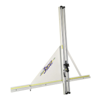
2. Set the Upper Measuring Stop Scale (A) (Figure 8) to the same border width as the
Locator Pin and lock it in place with Locking Knob B.
3. Slide the Upper Measuring Stop (D) toward the mat while holding the Spring
Button (C) down on the slip sheet. When the Spring Button touches the upper edge
of the mat, lock the Upper Measuring Stop in position with its Locking Knob (E).
4. Move the Cutting Head against the Stop Screw (F) on the Upper Measuring Stop.
Rotate the bevel cutting blade until it touches the mat. It should contact the mat about
1/8" (3mm) beyond the upper horizontal pencil line. If not, turn the Stop Screw in or out
until the blade is in the correct position. Lock the Stop Screw in place with its Jam Nut
(G).
5. Set the Lower Measuring Stop (H) at the same border width on its scale mounted on
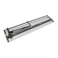
the top of the Clamp. See Figure 9. Starting at the upper position, insert the blade
through the mat. The right hand scribed line on the Magazine
(L), in Figure 10, should line up with the pencil line and the
Sight Gage should also be in line with the pencil line. Now
pull the Cutting Head toward the Lower Measuring Stop in
the usual way. It should hit the Lower Measuring Stop when
the blade has passed the lower horizontal line about 1/8”
(3mm). The left scribed line (M) on the Magazine should now
be in line with the pencil line, see Figure 11. lf necessary,
adjust the Stop Screw (J) on the Lower Measuring Stop to
achieve the 1/8" (3mm) dimension. Lock the Stop Screw (J) in
place by tightening its Jam Nut (K).
6. Proceed to cut out a complete mat. Cut both opposite sides first, then move the Upper
Measuring Stop to the top edge of the mat and cut the other two sides. Examine the
corners of the bevel cuts on the front side. The “fall-out” must be completely free and
the overcut barely visible. If not, adjust the appropriate Stop Screws. Too much overcut
requires moving the Stop Screw toward the Cutting Head. Incomplete corner separa-
tion (undercut) requires moving the Stop Screw away from the Cutting Head. Re-adjustment of the stop screws is
not required unless cutting a mat of different thickness.
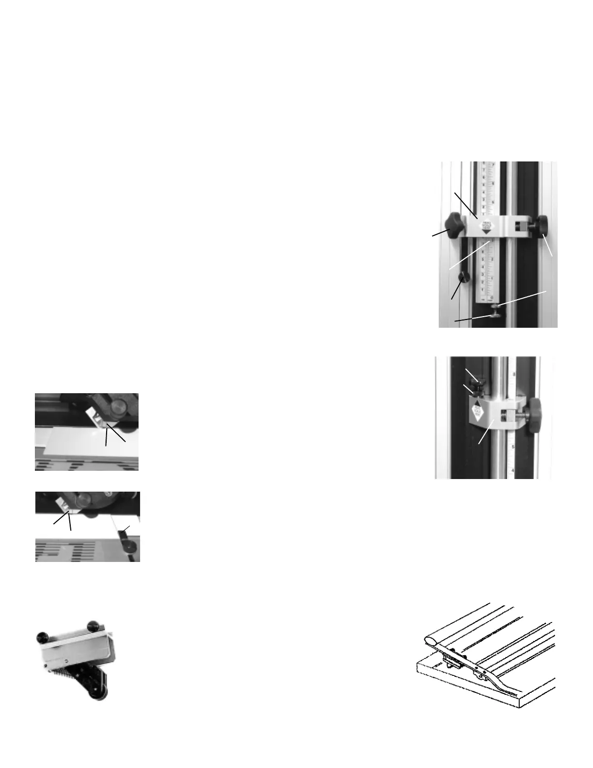
MAT CLAMP LIFTERS
Figure 8
A
B
C
D
E
G
F
H
J
K
Figure 9
Figure 10
L
M
Figure 11
N
Two Mat Clamp Lifters, (one shown at the left), are provided as an
option. Each is mounted on the underside of a Hinge Bracket with
the spring loaded roller resting on the Base as shown at the right.
This allows both hands to be free to position the slip sheet and mat. A
slight downward pressure on the Handle lowers the Mat Clamp to the mat.
65
GUÍA DE PASSE-PARTOUT CON ÁNGULOS
La Guía de passe-partout con ángulos es un agregado indispensable en la Fletcher 2200. Puede producir cortes en ángulos desde
los 15 grados hasta los 75 grados. Además del simple ángulo de 45 grados, se pueden producir fácilmente aberturas
con múltiples lados y con precisión. Sin importar la complejidad de la abertura, usted podrá crear passe-partout dobles con las
exposiciones del forro consistentes y exactas.
Juntar la Guía de passe-partout con ángulos a la Guía de passe-partout es simple en su Fletcher 2200. Vea la Figura 16.
El Gancho que traba (a) puede colocarse en cualquiera de los tres orificios (b). Al seleccionar el orificio de la izquierda, se
colocará la Guía de passe-partout con ángulos en el borde inferior de la Guía de passe-partout para passe-partout más
pequeños hasta 8" X 10" (200 mm X 250 mm). Al utilizar cualquiera de los dos orificios de la derecha, colocará la herramienta
hacia el borde superior de la Guía de passe-partout para passe-partout mayores.
Para juntarla, coloque la Guía de passe-partout con ángulos en la Guía de passe-partout y deslícela hacia abajo hasta que
se detenga. Se ubicará sobre la derecha de la Guía de passe-partout con dos proyecciones en la parte inferior y a la izquierda con el
Gancho que traba. Mientras sigue llevándola hacia usted, gire el Gancho que traba (a) en sentido contrario al de las agujas del reloj
para trabar firmemente la Guía de passe-partout con ángulos en su lugar. Para quitarla, gire el Gancho en el sentido de
las agujas del reloj.
1. La Figura 16 ilustra un corte en ángulo de 45 grados en un passe-partout de 8" x 10" (200 mm x 250 mm). Marcar las líneas
en lápiz sobre el revés del passe-partout en la forma convencional, comenzando con la guía de passe-partout en 1-1/2"
(38 mm) según lo muestran las líneas marcadas B.
2. Establezca ambos Brazos de ángulo de la Guía de passe-partout con ángulos en 45 grados. Coloque un triángulo de
90 grados entre ambos mientras se ajusta el Tirador que traba el ángulo (c). Utilice un ángulo del passe-partout en lugar
del triángulo si está bien en escuadra.
3. Establezca la Guía para
un borde de 3" (76 mm)
y utilice el Gancho como
final derecho, haga las
marcas en lápiz en el
revés del passe-partout,
como lo muestran las
líneas (A).
4. Ahora haga los 4
cortes (A), comenzando
y parando en las líneas
(B) para controlar los
sobre cortes. Asegúrese
que el ángulo del
passe-partout esté bien
apoyado sobre ambos
Brazos de ángulo
durante cada corte.
5. Quite la Guía de
passe-partout con
ángulos, reposicione
la Guía de passe-partout
en 1-1/2" (38 mm) y las
líneas de corte (B), utilice
los ángulos de corte que
se hicieron en el paso
4 para controlar los
sobre cortes.
CUBIERTA CONTRA EL POLVO
La Fletcher 2200 tiene una cubierta contra el polvo disponible. Es una opción práctica y recomendada para mantener la limpieza
y el trabajo de calidad de su cortadora.
a
b
A
A
B
B
B
B
c
Figure 16
A
A
 Loading...