9
RIGHT SQUARING ARM
This option will speed up the production of mats by giving you exact down-sizing of matboard. Its sturdy construction and
bracing will assure accurate sizes and 90 degree corners, so important to fine mat work.
Tools required: phillips screwdriver, 5/32" hex wrench, and adjustable wrench.
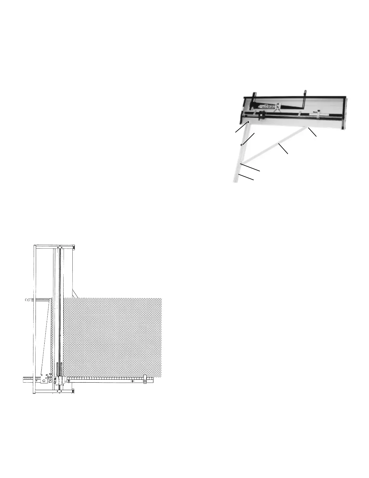
You will receive the Right Squaring Arm components disassembled into three parts, the Right Squaring Arm (A) with
an inch/metric scale, the Angle Brace (B), a Squaring Arm Stop (C) and
fasteners. See Figure 12.
1 . The Fletcher 2200 should be resting on a flat surface large enough to
provide support for the Right Squaring Arm. You will see a hole in the
Base about 5" from the near end (D). Assemble the flat head screw,
from the parts bag, through the Right Squaring Arm and the Base.
Place the washer, lock washer, and hex nut on the screw from beneath
the Base and tighten.
2. On the right edge of the Base about 40" from the near end, you will find
a button head screw (E) which is threaded into a nut in the Base.
Remove the screw with the 5/32” hex wrench. Leave the nut in the
Base. At the upper end of the Angle Brace, you will see a hole in a
bracket. Connect this bracket to the edge of the Base using the button
head screw and nut. Tighten the screw only slightly.
3. Remove the flat head screw and eccentric hex nut from the parts bag. Assemble this screw and eccentric nut through
the Right Squaring Arm and the hole in the end of the Angle Brace (B). Be sure the eccentric nut (F) is fully seated
in the 7/16" hole in the Angle Brace. Leave it slightly loose.
4. Turn the hex eccentric nut with your fingers. You will notice the Right Squaring Arm move up and down with respect
to the Angle Brace. At about halfway in this motion, tighten the
flat head screw while holding the eccentric nut.
5. The Mat Guide should be locked in position on the Mat Guide
Slide. Place a full size mat (32x40) horizontally on the Base
with the lower edge resting against the Squaring Arm. Note, it is
not placed on top of the scale. Slide the mat to the left so it
touches the Mat Guide evenly along the full length of the Mat
Guide. You will note the mat is probably not in contact along the
full length of the Right Squaring Arm. Slide the upper end of
the Angle Brace, under the button head screw, until the mat is in
full contact with both the Mat Guide and Right Squaring Arm.
See Figure 13.
6. Slightly loosen the flat head screw at the joint of the Squaring
Arm and Angle Brace. While holding the screw with a screw-
driver, rotate the eccentric nut slowly until the bottom edge of the
mat is in contact along the full length of the Squaring Arm and
the Mat Guide. Now, tighten the flat head screw without letting
the eccentric nut turn. Also tighten the nut under the Base
at the end of the Right Squaring Arm and the button head
screw which holds the Angle Brace to the right side of the Base.
If you are unable to obtain the square condition with this adjustment, slide the Angle Brace where it is attached with
the button head screw and repeat the eccentric nut adjustment. Be sure all screws are well tightened and then re-
check squareness by bringing the mat into contact with both the Right Squaring Arm and the Mat Guide at the
same time.
A
B
C
D
E
F
Figure 12
Figure 13
64
7. La escala en el Brazo en escuadra tiene un adhesivo sensible a la presión en
la parte inferior. Deslice la escala hacia las pulgadas correctas. Pele 4" del papel protec-
tor del adhesivo y deslice la escala nuevamente hacia la izquierda, pero no coloque el
adhesivo todavía. Vea la Figura 14.
8. Dibuje una línea vertical a 3" del borde izquierdo del passe-partout.
Coloque el borde inferior del passe-partout contra el Brazo en escuadra y deslícelo
suavemente hacia la izquierda hasta hacer contacto la cuchilla vertical que deberá
girarse hacia abajo. La escala debe posicionarse de tal forma que esté en línea
con la marca hecha en lápiz con el índice de 3" de la escala. Presione sobre el borde
derecho de la escala para que se adhiera al Brazo en escuadra. Si fuera necesario
reposicionar la escala, debería ser fácil quitar la sección adherida y reubicar la escala.
EXTENSIÓN DE LA BASE
Figura 14
1. Quite la Guía (A), la Guía de deslizamiento (B) y el Soporte (C) del lado izquierdo
de la Base. Quite los sujetadores a un lado para poder usarlos nuevamente.
2. Quite ambas Tapas de los extremos (D) de la máquina y guárdelas.
Quite los tornillos y déjelos a un lado para poder usarlos nuevamente.
3. Se proveen tres juegos de tornillos y tuercas. Sólo se necesitan dos juegos para
los modelos 40" y 48". Inserte los tornillos de cabeza cilíndrica a través
de los orificios sobre el borde izquierdo de la Base dejando que sobresalgan las
roscas. Atornille las tuercas cuadradas en los tornillos con sólo un o dos giros.
Deben estar bien flojos por ahora.
4. Deslice la Extensión de la base opcional sobre las tuercas. Verá que las tuercas cuadradas entran en una ranura sobre el lado
derecho de la Extensión de la base. Alinee ambos extremos de los miembros de la base y ajuste los tornillos con las tuercas
cuadradas. Utilice la llave hexagonal que se provee con la máquina.
5. Monte las nuevas Tapas de los extremos utilizando los tornillos que se han descartado y otros de la bolsa de las piezas.
Una los tres botones de goma que se encuentran en la bolsa de las piezas a las varillas inferiores de la Extensión de base.
6. Instale la nueva y más larga Guía de deslizamiento en la Base, utilizando los sujetadores de la anterior. Deslice la Guía dentro
de la Guía de deslizamiento y vuelva a instalar el Soporte sobre el borde de la izquierda de la Extensión de base. Encuadre la
máquina como lo indica la sección de ajustes de este manual.
7. Se proporciona una nueva y más larga Parada de medida superior en los casos que utilice la opción de Parada de medida.
Simplemente cambiarla en la Parada de medida superior. También se proporcionan unas escalas más largas en sistema métrico
e inglés para reemplazar aquellas que están arriba del Gancho de passe-partout para permitirle establecer Medidas de parada
inferiores para passe-partout con dimensiones de bordes mayores. Si desea instalar estas nuevas escalas, marque el Gancho
de passe-partout en la posición cero antes de quitar la escala anterior. De esta forma podrá colocar fácilmente la nueva escala.
8. La nueva Extensión de base tiene un orificio alineado con la Correa que traba a la guía de passe-partout. Quizás desee
montar el Tirador superior sobre la Extensión de la base. Esto acomodará las mismas dimensiones de los bordes del passe-
partout como la máquina estándar. Cuando se necesitan bordes de passe-partout mayores, el Tirador superior
puede moverse hacia el Soporte en el lado izquierdo de la Extensión de la base.
Figura 15
A
B
C
D
 Loading...