6 Installation FLUXUS F70x
UMFLUXUS_F7V4-6-2EN, 2017-10-01 29
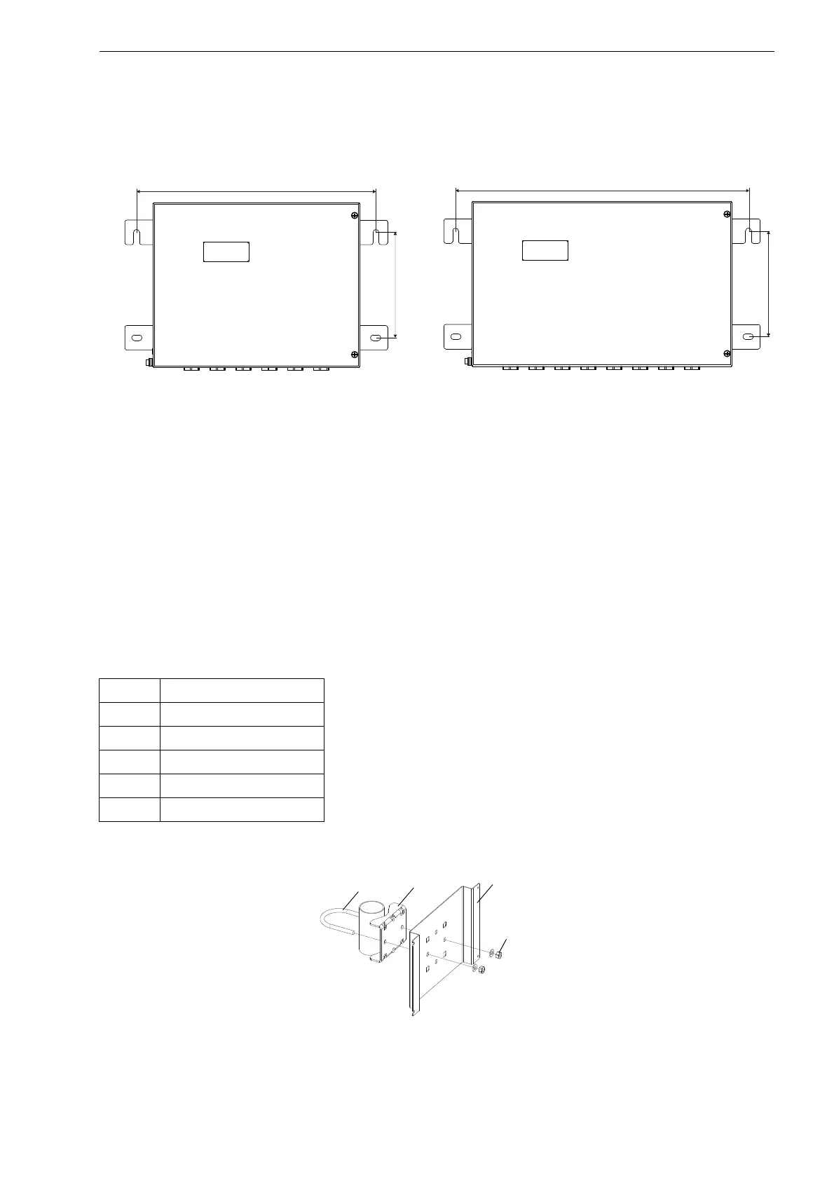
FLUXUS F705, F706
• Fix the transmitter to the wall (see Fig. 6.2 and Fig. 6.3).
6.2.3 Pipe Installation
Installation on a 2" pipe
The mounting kit is fixed to the pipe using a shackle.
• Fix the pipe mounting plate (2) and the instrument mounting plate (3) to the pipe using the nuts (4) and the shackle (1)
(see Tab. 6.1 and Fig. 6.4).
• Use the screws to fix the transmitter to the instrument mounting plate (see Fig. 6.5 or Fig. 6.6).
Installation on a pipe > 2"
The mounting kit is fixed to the pipe using tension straps.
• Insert the tension straps into the holes of the pipe mounting plate (2) and the instrument mounting plate (3) (see Tab. 6.1
and Fig. 6.7).
• Fix the pipe mounting plate and the instrument mounting plate to the pipe using the tension strap.
• Use the screws to fix the transmitter to the instrument mounting plate (see Fig. 6.5 or Fig. 6.6).
Fig. 6.2: FLUXUS F705 (dimensions in mm) Fig. 6.3: FLUXUS F706 (dimensions in mm)
Tab. 6.1: Parts of the mounting kit
number designation
1 shackle
2 pipe mounting plate
3 instrument mounting plate
4nut
5 tension strap
Fig. 6.4: Installation of the instrument mounting plate
 Loading...


