8
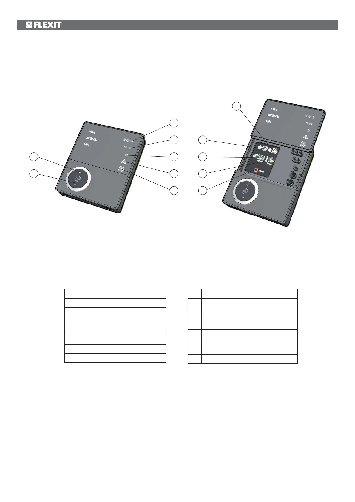
3 Overview of CI60 control panel
3
4
5
6
7
1
*
2
8
9
10
11
12
No. Description
1
*
Switch for increased ventilation
2 Switch for decreased ventilation
3
Indication of MAX speed
4
Indication of NORMAL speed
5
Indication of MIN speed
6
Indication of ALARM
7
Indication of FILTER CHANGE
No. Description
8 Potentiometer for adjusting extract air
at NORMAL speed
9 Potentiometer for adjusting supply air at
NORMAL speed
10
Switch for additional heating ON/OFF
11 Potentiometer for adjusting supply air
temperature
12 Switch to reset alarm
*The numbers are used as references in subsequent descriptions
Nos. 8, 9 and 10 are used to adjust the unit before it
is used for the first time.
Fig. 20