9
Fig. 21
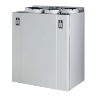
4 CI60 in use
4.1 General
The control unit consists of a touch panel with pushbuttons,
LEDs for indication and adjustment potentiometers and
switches for adjusting the ventilation unit. The control unit
communicates with the ventilation unit via a low-voltage
cable.
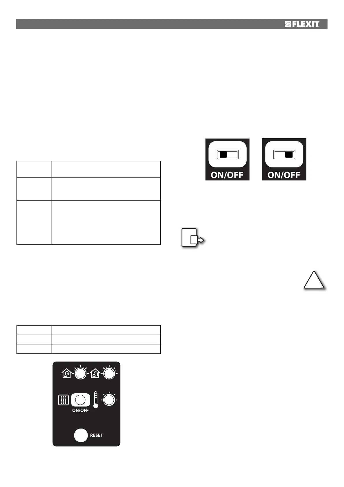
4.2 Increasing/reducing air supply
Use switches 1 and 2 to increase and reduce the fan speed
and thus the air flow. Different speeds depending on the
operating situation.
MIN
Do not use during first year of operation, or
when the building is in use.
NORMAL
Used under normal conditions. In this
setting, the air supply must be adjusted
according to current regulations.
MAX
Used if there is a need for increased air
supply on account of increased occupancy
or a higher humidity level, for example
during showering or when clothes are being
dried. This setting is usually used for limited
periods of time.
The different speeds are indicated with LEDs 3, 4 and 5.
4.3 Adjusting the air supply
At NORMAL speed level, the air flow must be adjusted
according to project data. Potentiometer 9 is used for the
supply air level and potentiometer 8 for the extract air level.
The adjustment range is 20-100% of the maximum level
according to the scale of the potentiometer.
Factory settings:
MIN
50% (fixed)
NORMAL
75% (variable)
MAX
100% (fixed)
4.4 Temperature adjustment
The temperature required in the supply air can be set with
potentiometer 11. The adjustment range is 10 - 30 °C. Using
the factory settings is recommended.
If necessary, the ventilation unit’s heating can also be
switched ON/OFF with switch 10. In this case only the rotating
heat exchanger is used as a source of heat. It is best to leave
it in ON position, as the unit will then respond automatically
when there is a need for additional heating.
4.5 Filter replacement
Every six months, LED 7 lights up to remind you that it is time
to replace the air filters in the unit. See section 2 for more
information on filter r
eplacement.
After the activity has been carried out, the
indicator must be reset. See more under the
Reset section.
4.6 Alarm
If anything unforeseen occurs with the
ventilation unit, indicator 6 lights up.
The signal given by the indicator depends on the
reason for the indication.
A permanent light indicates:
• Fault return water detector (B5)
• Heat recovery fault (B)
A permanent light with indicator 5 (MIN speed) flashing
indicates:
• Fault supply air detector (B1)
• Fault extract air detector (B3)
• Fault outdoor air detector (B4)
A flashing light indicates:
• Overheating thermostat fault (applies only to electric hea-
ting)
• Fault in external fire/smoke detector (accessory)
• Heat recovery fault (A)
• Additional heating fault (applies only if the unit has a water
battery)
!
8
9
10 11
ON
OFF
ITEM 10