Pin configurations and
schematics
14
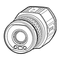
14.1 M12 connector pin configuration
This section specifies the pin configuration for the M12 connector at the rear of the
camera.
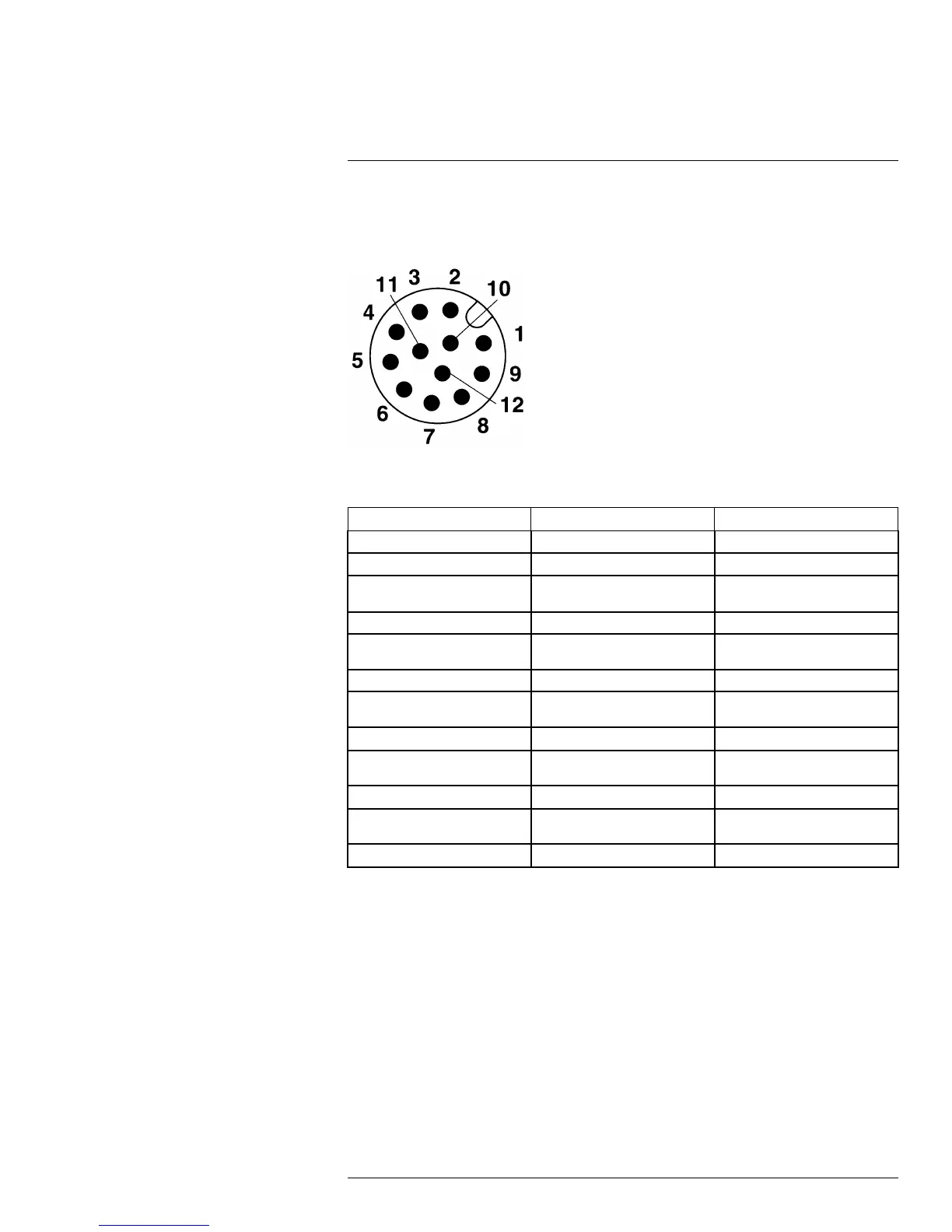
Figure 14.1 Pin assignment M12 male connector: 12 positions, male side view.
Table 14.1 Mapping table, pin to signal
Pin Signal Explanation
1
RET_GB Camera PWR –
2
PWR_GB Camera PWR +
3
SYNC_OUT LVC Buffer @ 3.3 V, ”0” = 24 MA
max, “1” = –24 mA max.
4
SYNC_OUT_GND = RET_GB = Camera PWR –
5
SYNC_IN LVC Buffer @ 3.3 V, “0” < 0.8 V,
“1” > 2.0 V
6
SYNC_IN_GND = RET_GB = Camera PWR –
7
GPO+ 1 × opto-isolated, 2–40 VDC,
max. 185 mA
8
GPO– = GP Input return
9
GPIO_PWR GP Output PWR. 2–40 VDC,
max. 200 mA
10
GPIO_GND GP Ouput PWR return
11
GPI+ 1 × opto-isolated, “0” < 2, “1” =
2–40 VDC
12
GPI- GP Input return
Cables for the M12 connector are available from FLIR Systems. See the part numbers
below.
• T127605, Cable M12 pigtail.
• T127606, Cable M12 sync.
#T559770; r. AF/30726/30726; en-US
103
 Loading...