Mechanical installation
7
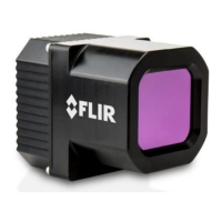
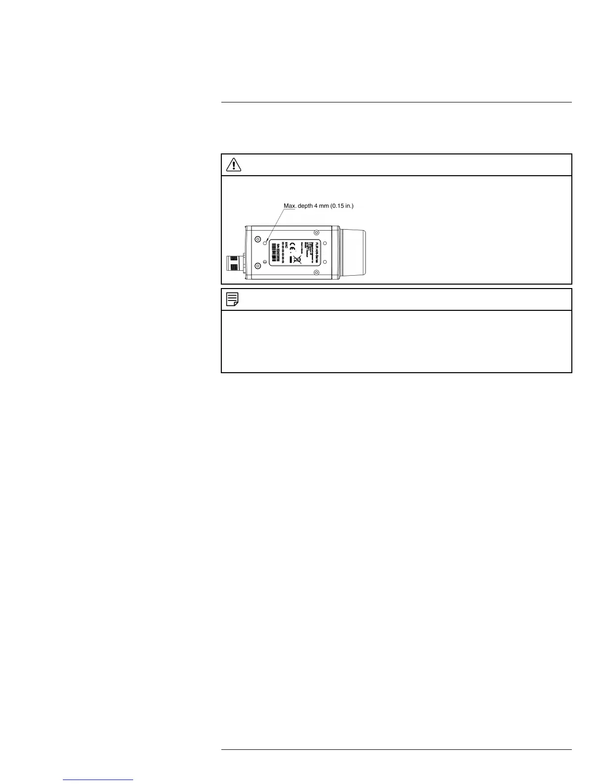
The camera unit has been designed to allow it to be mounted in any position. It has a
mounting interface on the bottom with four metric M3 holes.
WARNING
Do not use screws that are too long. Using screws that are too long will damage the camera. The maxi-
mum depth of the M3 holes is 4 mm (0.15 in.).
NOTE
The camera generates a considerable amount of heat during operation. This is normal. In order to trans-
fer this heat, it is recommended that the camera is mounted on a base support or a heat sink made of a
material that has a high capacity to transfer heat, e.g., aluminum. FLIR Systems provides P/N T198349
(base support) for this purpose, but other base supports or heat sinks can be used.
The use of the base support is also strongly recommended in order to minimize temperature drift of the
infrared detector in the camera.
If the camera unit is to be permanently mounted on the application site, certain steps have
to be taken. The camera unit might need to be enclosed in a protective housing and, de-
pending on the ambient conditions (e.g., temperature), the housing may need to be cooled
by means of water or air. In very dusty conditions the installation might also need to have a
stream of pressurized air directed at the lens, in order to prevent dust build-up.
When mounting the camera unit in harsh environments, every precaution should be taken
when it comes to securing the unit. If the environment exposes the unit to severe vibra-
tions, there may arise a need to secure the mounting screws by means of Loctite or anoth-
er industrial brand of thread-locking liquid, as well as to dampen the vibrations by
mounting the camera unit on a specially designed mounting base.
For further information regarding mounting recommendations and environmental enclo-
sures, contact FLIR Systems.
The camera is typically powered using PoE (Power over Ethernet). A PoE injector and ca-
ble kit are available from FLIR Systems. See the part numbers below.
• T198348, Cable kit mains (UK, EU, US).
• T911112, PoE injector.
• T951004ACC, Ethernet cable CAT-6, 2 m/6.6 ft.
#T559770; r. AF/30726/30726; en-US
12
 Loading...