Home
FLIR
Thermal cameras
A15
FLIR A15 User Manual
4
of 1
of 1 rating
156 pages
Give review
Manual
Specs
To Next Page
To Next Page
To Previous Page
To Previous Page
Loading...
Pin
configurations
and
schematics
14
14.2
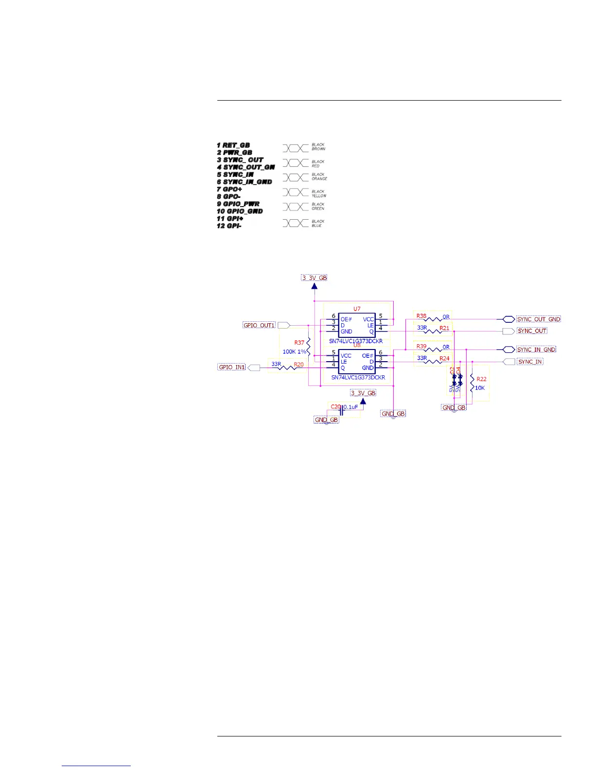
Pig-tail
end
of
cable
Figure
14.2
Mapping
table,
signal
type
to
cable
color.
14.3
SYNC
input/output
schematics
Figure
14.3
Schematics
of
S
YNC
input
and
output.
#T559770;
r
.
AF/30726/30726;
en-US
104
111
113
Table of Contents
Default Chapter
5
Table of Contents
5
1 Legal Disclaimer
9
Usage Statistics
9
Changes to Registry
9
Government Regulations
9
Copyright
9
Quality Assurance
10
Patents
10
EULA Terms
10
2 Safety Information
12
3 Notice to User
13
User-To-User Forums
13
Calibration
13
Accuracy
13
Disposal of Electronic Waste
13
Training
13
Documentation Updates
13
Important Note about this Manual
13
Note about Authoritative Versions
14
4 Customer Help
15
General
15
Submitting a Question
16
Downloads
16
5 Introduction
17
6 List of Accessories and Services
18
7 Mechanical Installation
20
8 Focusing the Camera
21
Focusing Cameras with 5, 9, 13, and 19 MM Lenses
21
Necessary Tools
21
Procedure
21
Focusing Cameras with 25 MM Lenses
22
Necessary Tools
22
Procedure
22
9 Downloads
23
10 About I/O, Synchronization, and Measurement
24
FLIR Ax5 General Purpose I/O
24
FLIR Ax5 Synchronization
24
FLIR Ax5 Measurement
25
11 Technical Data
28
Online Field-Of-View Calculator
28
Note about Technical Data
28
Note about Authoritative Versions
28
FLIR A15 F=19 MM
29
FLIR A15 F=19 MM (7.5 Hz)
33
FLIR A15 F=9 MM
37
FLIR A15 F=9 MM (7.5 Hz)
41
FLIR A15 F=9 MM with SC Kit (7.5 Hz)
45
FLIR A35 F=19 MM
49
FLIR A35 F=9 MM
53
FLIR A35 F=9 MM with SC Kit
57
FLIR A5 F=5 MM
61
FLIR A5 F=5 MM (7.5 Hz)
65
FLIR A5 F=5 MM with SC Kit (7.5 Hz)
69
FLIR A5 F=9 MM
73
FLIR A5 F=9 MM (7.5 Hz)
77
FLIR A65 F=13 MM
81
FLIR A65 F=13 MM (7.5 Hz)
85
FLIR A65 F=13 MM with SC Kit (7.5 Hz)
89
FLIR A65 F=25 MM
93
FLIR A65 F=25 MM (7.5 Hz)
97
12 Mechanical Drawings
101
13 CE Declaration of Conformity
109
14 Pin Configurations and Schematics
111
M12 Connector Pin Configuration
111
Pig-Tail End of Cable
112
SYNC Input/Output Schematics
112
GP Input/Output Schematics
113
15 Cleaning the Camera
114
Camera Housing, Cables, and Other Items
114
Liquids
114
Equipment
114
Procedure
114
Infrared Lens
114
16 About FLIR Systems
115
More than Just an Infrared Camera
116
Sharing Our Knowledge
116
Supporting Our Customers
117
17 Glossary
118
18 Thermographic Measurement Techniques
121
Introduction
121
Emissivity
121
Finding the Emissivity of a Sample
121
Reflected Apparent Temperature
125
Distance
125
Relative Humidity
125
Other Parameters
125
19 History of Infrared Technology
126
20 Theory of Thermography
129
Introduction
129
The Electromagnetic Spectrum
129
Blackbody Radiation
129
Planck's Law
130
Wien's Displacement Law
131
Stefan-Boltzmann's Law
133
Non-Blackbody Emitters
133
Infrared Semi-Transparent Materials
135
21 The Measurement Formula
137
22 Emissivity Tables
141
References
141
Tables
141
4
Based on 1 rating
Ask a question
Give review
Questions and Answers:
Need help?
Do you have a question about the FLIR A15 and is the answer not in the manual?
Ask a question
FLIR A15 Specifications
General
Brand
FLIR
Model
A15
Category
Thermal cameras
Language
English
Related product manuals
FLIR ADK
27 pages
FLIR A65
156 pages
FLIR A615
124 pages
FLIR A655sc
124 pages
FLIR A6 Series
124 pages
FLIR A700 Series
67 pages
FLIR A500 Series
69 pages
FLIR K2
56 pages
FLIR ONE
15 pages
FLIR E75
328 pages
FLIR T530
248 pages
FLIR Scout
38 pages