FLIR ADK
Getting Sta rt e d
The information contained herein does not contain technology as
defined by EAR,15 CFR772, is publicly available, and therefore
not subject to EAR.
16
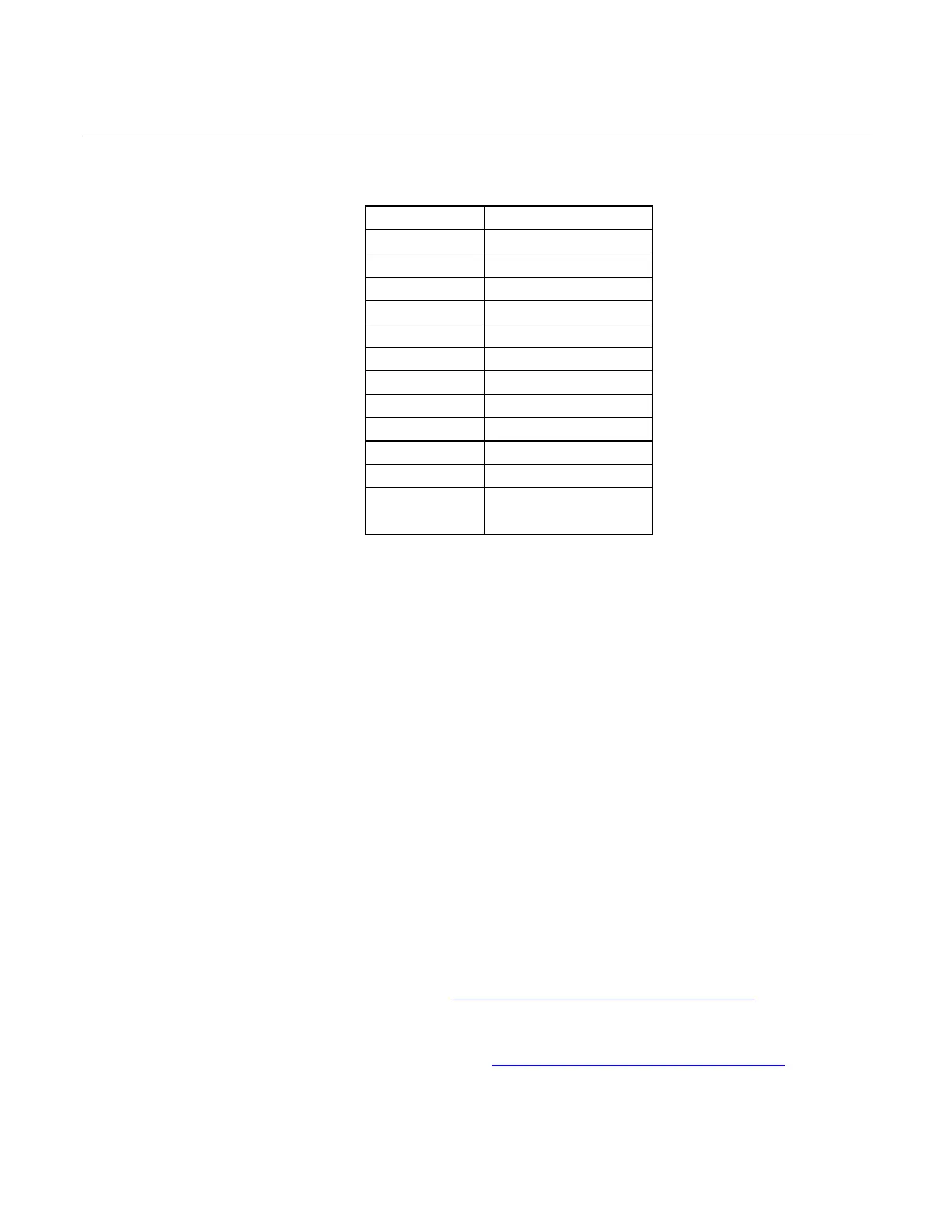
Table 2: The Boson and Maxim 9295A pin correlation.
4.5 Sending Commands to the ADK over i2C
Currently the Boson camera core of the ADK will only communicate via UART. The GMSL
adapter board in the ADK has an i2C to UART FIFO transceiver that will allow you to send
byte array commands to the Boson. In practice, the I2C to UART buffer limits the amount of
data you can send to the Boson at any one time to 128 bytes. The I2C to UART transceiver
has the 8-bit address 0xD8.
The standard cycle for sending I2C commands to the boson is:
1) Turn off the transmitter on the I2C to UART transceiver.
a. Write value 0x02 to register 0x09 to device 0xD8.
2) Send a series of I2C commands to the FIFO buffer.
a. For each value in command byte array. Write value to register 0x00 to device 0xD8
3) Turn on the transmitter on the I2C to UART transceiver – this flushes the FIFO buffer to the
Boson.
a. Write value 0x02 to register 0x09 to device 0xD8.
Note: there are example i2cWrite, i2cRead, and sendCommand functions for a teensy board
connected to the Maxim deserializer in Sample I2C Functions For Teensy SOC.
To generate the command byte arrays to send to the Boson, customers can use the rawBoson
tool provided through FLIR on GitHub at https://github.com/FLIR/rawBoson combined
with the Boson SDK documentation/Software IDD. The Software IDD describe the command