FLIR LEPTON® Engineering Datasheet
The information contained herein does not contain technology as defined by the EAR, 15 CFR 772, is publicly available,
and therefore, not subject to EAR. NSR (6/14/2018).
Information on this page is subject to change without notice.
Lepton Engineering Datasheet, Document Number: 500-0659-00-09 Rev: 203
11
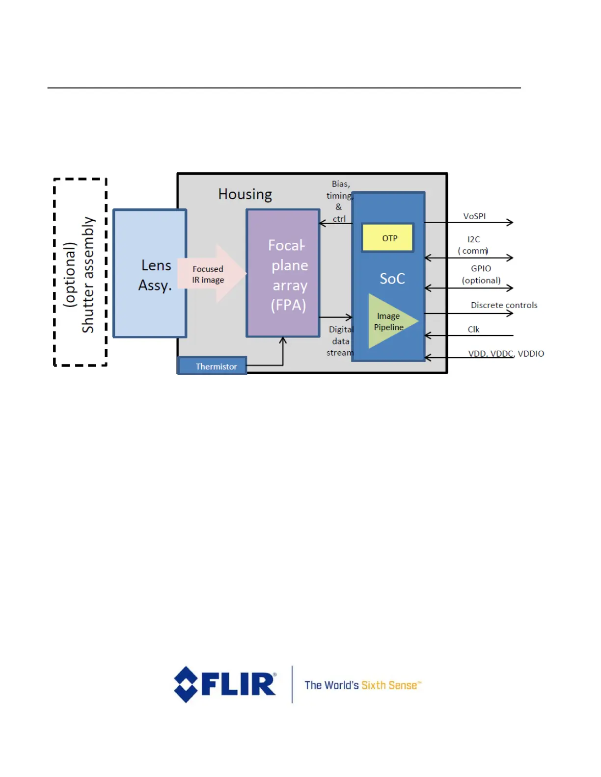
1.6 System Architecture
A simplified architectural diagram of the Lepton camera module is shown in Figure 2.
Figure 2 - Lepton Architecture
The lens assembly focuses infrared radiation from the scene onto an array of thermal detectors with
17m or
12m pitch. Each detector element is a vanadium-oxide (VOx) microbolometer whose temperature
varies in
response to incident flux. The change in temperature causes a proportional change in each
microbolometer’s
resistance. VOx provides a high temperature coefficient of resistance (TCR) and low 1/f
noise, resulting in excellent
thermal sensitivity and stable uniformity. The microbolometer array is grown
monolithically on top of a readout
integrated circuit (ROIC) to comprise the complete focal plane array (FPA).
For shuttered configurations, the shutter assembly periodically blocks radiation from the scene and presents a
uniform thermal
signal to the sensor array, allowing an update to internal correction terms used to improve image
quality. For
applications in which there is little to no movement of the Lepton camera relative to the scene (for
example,
fixed-mount security applications), the shutter assembly is recommended. For applications in which
there is
ample movement (for example, handheld applications), the shutter assembly is less essential although still
capable of providing slight improvement to image quality, particularly at start-up and when the ambient
temperature varies rapidly. The shutter is also used as a reference for improved radiometric performance.