FLIR LEPTON® Engineering Datasheet
The information contained herein does not contain technology as defined by the EAR, 15 CFR 772, is publicly available,
and therefore, not subject to EAR. NSR (6/14/2018).
Information on this page is subject to change without notice.
Lepton Engineering Datasheet, Document Number: 500-0659-00-09 Rev: 203
12
The serial stream from the FPA is received by a system on a chip (SoC) device, which provides signal
processing and
output formatting. This device is more fully defined in Functional Description, page 12.
2 Functional Description
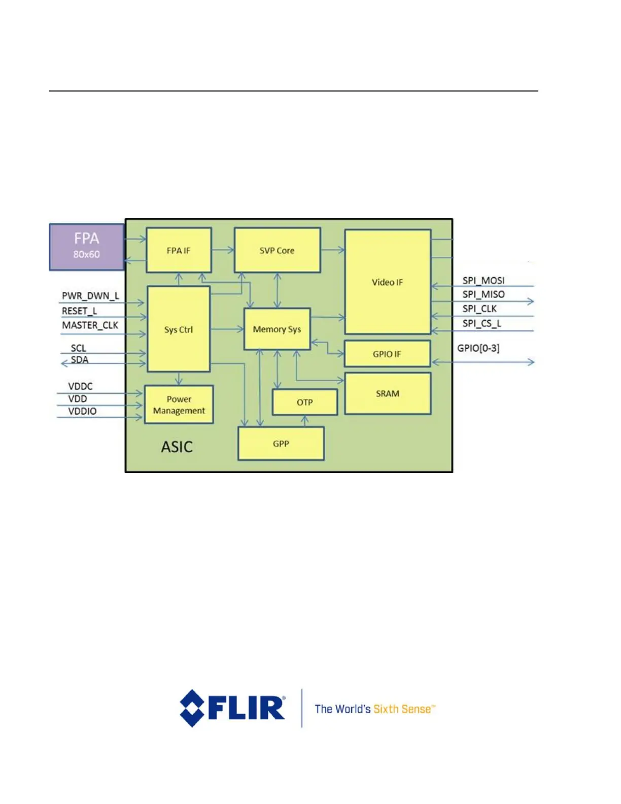
A detailed block diagram of the Lepton camera module is shown in Figure 3.
Figure 3 - Lepton Detailed Block Diagram
2.1 FPA Interface Module
The FPA Interface module generates timing and control signals to the FPA. It also receives and deserializes the
digital data stream from the FPA. The output values of on-board temperature sensors are multiplexed into the
pixel data stream, and the FPA Interface module strips these out and accumulates them (to improve SNR).
2.2 System Control (Sys Ctrl) Module
The System Control module provides the phase-lock-loop (PLL) and generates all clocks and resets required for
other modules. It also generates other timing events including syncs and the internal watchdog timer.
Additionally, it provides the boot controller, random-number generator, and command and control interface (CCI)
decode logic.