REPLACING BATTERIES
Always replace both batteries at the same time with the
same size, brand, and preferably the same lot number.
Unmatched batteries and from different lots will cause a
constant drain on the batteries and shorten the life of the
batteries.
SEASONAL BATTERY STORAGE
Fully charge the battery according to the manufacturer’s
instructions.
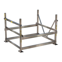
LIMIT SWITCH CONNECTION AND
IMPORTANT INFORMATION
The VSD system is equipped with automatic upper and
lower magnetic safety limit switches. The magnets for
these switches are mounted to the ball nut and travel with
it along the rotating ball screw (see Fig. 3 on page 6).
The limit switches are contained within an aluminum
housing as shown in Fig. 12.
As the ball nut and its magnets pass over a limit switch,
the magnetic force trips the switch. Once a limit switch is
triggered, it prevents the drive-train system from going
beyond its normal extended or retracted travel limits.
Exceeding these limits will cause severe damage to the
lift or drive-train system.
Fig. 12 Limit Switch Housing
Charging Option #1
To charge the batteries with a 12-volt deep cycle charger,
remove the battery box lids to access the battery posts
and charge each battery individually, as you would
normally. Connect the charger’s positive (red) clamp to
the positive terminal on Battery #1, then connect the
negative (black) clamp to the negative terminal on Battery
#1. Repeat these steps for Battery #2.
Charging Option #2
To charge both batteries at once, use a 24-volt DC deep
cycle charger. A charger that meets this criteria is a
Schumacher SE-10MA 12/24 volt deep cycle charger,
which can be found at www.batteries.com. Follow these
simple steps:
Step 1: Remove the battery box lids. Connect the
charger’s positive (red) clamp to the positive post on
Battery #2. (See Fig. 7)
Step 2: Connect the negative (black) clamp to the
negative terminal of Battery #1. Charge the batteries
per manufacturers’ instructions for both the battery and
the charger.
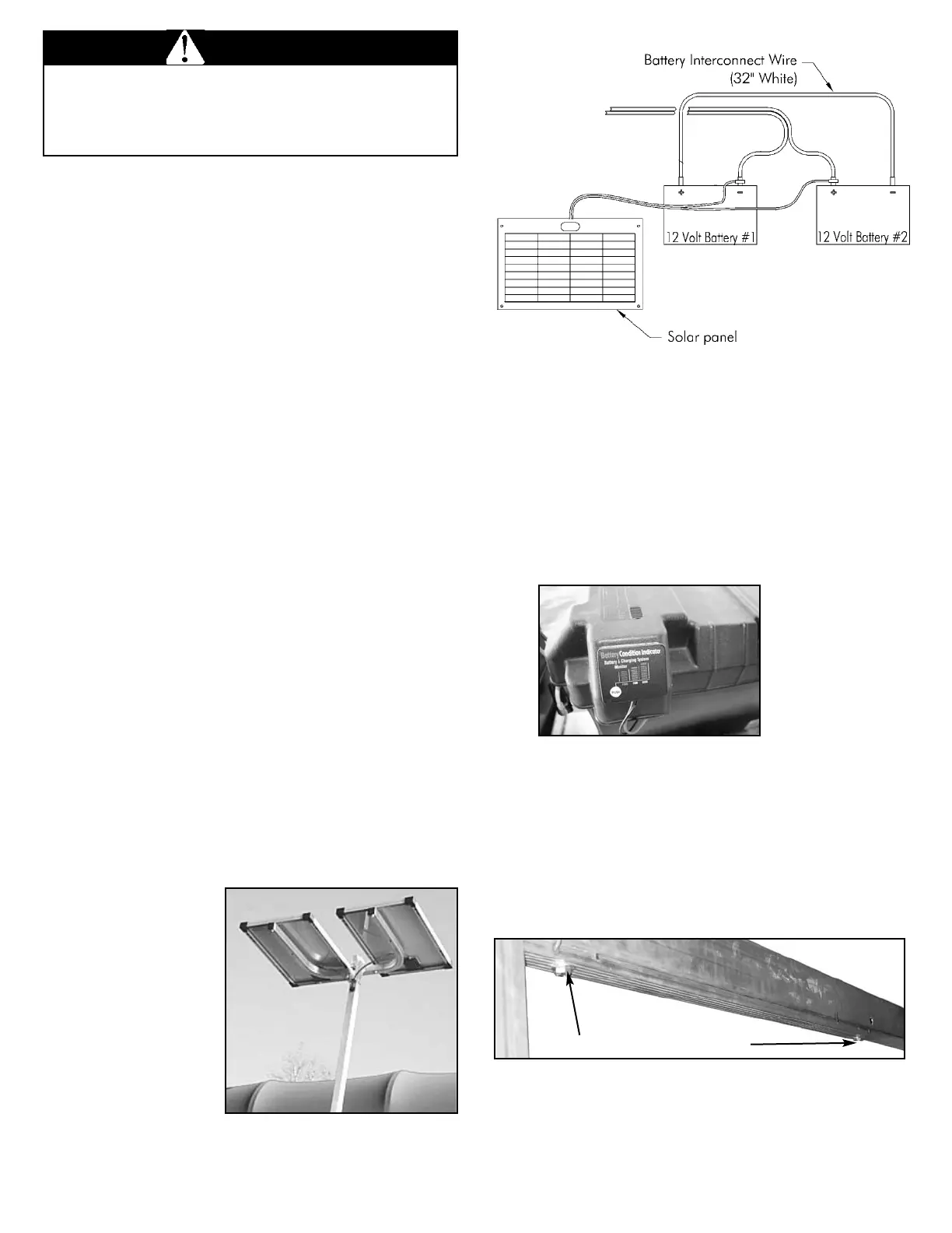
Note: You will attach the charger’s clamps to the same
battery posts that the cables coming from the drive train
box control panel use. The same applies to the solar
panel hook-up shown in Fig. 10. Never attach the
connectors for the charger or solar panel to the same
battery terminals used by the white interconnect-
battery wire.
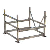
Charging Option #3 - To maintain battery charge with the
optional FLOE 24-Volt solar panels, mount panels per
included instructions and wire it to the batteries as shown
in Fig. 10. Be sure the panels faces the sun during peak
daylight hours. A solar panel provides continuous
charging on sunny
days. A 24V system is
shown in Fig 11. A
corner post mount is
also available for lifts
without canopy
systems.
NOTE: Solar panels
will only maintain a
charge on batteries.
Be sure batteries are
fully charged before
installing a solar panel.
When charging batteries, it is important to follow the
manufacturer’s instructions for both the battery and
charging systems to ensure that batteries are not
damaged by improper or over charging.
WARNING
Fig. 11
24 volt Solar Panel
To electronic
control box
To electronic
control box
Fig. 10
Solar Panel
& Battery
Diagram
SIDE VIEW
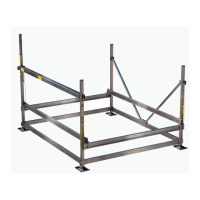
blackblack red
Battery boxes
include a built
in battery
condition
indicator to let
you know the
level of your
charge.
11