4
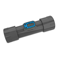
Information specific to your particular
turbine, including serial number, model
number, manufacturing date, and
K-factor is etched on the meter. Be pre-
pared to provide this information if you
call customer service.
SN = Serial Number, a 6-digit number
that identifies this particular turbine.
MODEL = Model Number, G2 followed
with a letter indicating the housing ma-
terial.
A for Aluminum
S for Stainless Steel
Two digits follow the material code indi-
cating the size.
05 – 1/2 inch
07 – 3/4 inch
10 – 1 inch
15 – 1-1/2 inch
20 – 2 inch
The final letter indicates the type of
thread.
F for Flange
N for NPT
I for ISO
T for Tri-Clover® Flange
MFG DATE = Manufacturing Date in-
dicating the week and year of manufac-
ture.
KF = K-Factor given in pulses per gal-
lon (PPG).
INSTALLATION
For your future reference, it might be
useful to record this information in the
manual in case it becomes unreadable
on the turbine.
All FLOMEC® turbines are designed to
measure flow in only one direction. The
direction is indicated by the arrow,
cast-molded in the turbine.
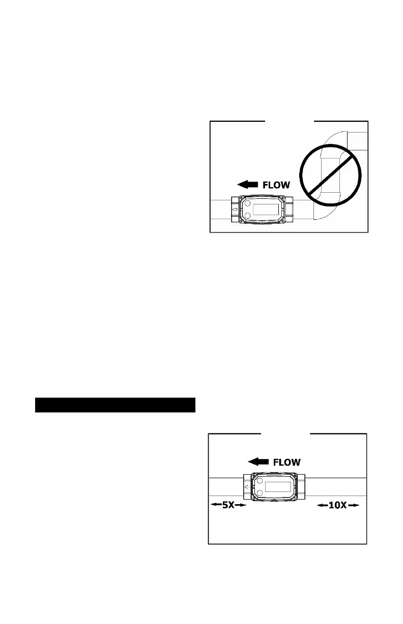
Flow altering devices such as elbows,
valves, and reducers can affect accu-
racy. See Diagram 1. The following rec-
ommended guidelines are given to en-
hance accuracy and maximize perfor-
mance. Distances given here are mini-
mum requirements; double them for
desired straight pipe lengths.
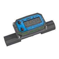
Upstream from the turbine, allow a min-
imum straight pipe length at least 10
times the internal diameter of the tur-
bine. For example, with the 1-inch tur-
bine, there should be 10 inches (25.4
cm) of straight pipe immediately up-
stream. The desired upstream straight
pipe length is 20 inches (50.8 cm).
Downstream from the turbine, allow a
minimum straight pipe length at least 5
times the internal diameter of your tur-
bine. For example, with the 1-inch tur-
bine, there should be 5 inches (12.7
cm) of straight pipe immediately down-
stream. The desired downstream dis-
tance is 10 inches (25.4 cm). See Dia-
gram 2.