16
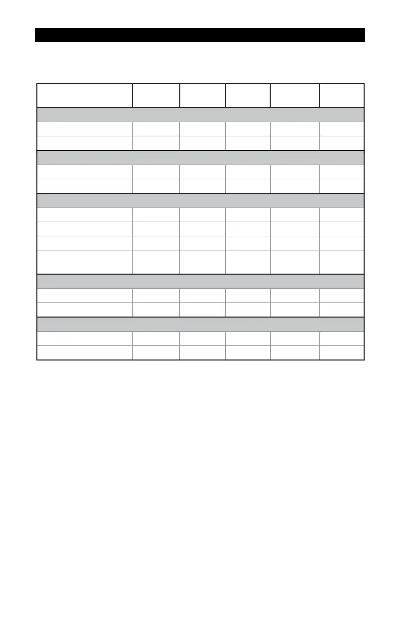
SPECIFICATIONS – TRI-CLOVER® FLANGE FITTINGS
All data on Models 1/2 inch, 3/4 inch and 1 inch determined with 1 centipoise solvent test fluid at
70° F (21° C). Data on Models 1-1/2 inch and 2 inch is determined with water at 70° F (21° C).
Size refers to the size of the turbine, not the body ferrule. Refer to dimension chart for detail sizes.
Model Size
1/2 in.
3/4 in.
1 in.
1
1/2 in.
2 in.
Linear Flow Range
Gallons/minute (GPM) 1-10 2-20 5-50 10-100 20-200
Litres/minute (LPM) 3.8-37.9 7.6-75.7 18.9-190 38-380 76-760
Maximum Flow
Gallons/minute (GPM) 15 30 75 150 300
Litres/minute (LPM) 56.8 113.6 284 568 1,136
Maximum Pressure Drop
in 10:1 Range
PSIG 8 7.5 5 4 4
bar 0.55 0.52 0.34 0.28 0.28
Frequency Range in Lin-
ear Flow Range
45-450 Hz 37-370 Hz
45-475 Hz
35-350 Hz 33-330 Hz
Connections
Inlet/Outlet Size 1/2 in. 3/4 in. 1 in. 1-1/2 in. 2 in.
Fitting Clamp Size 3/4 in. 1 in. 1-1/2 in. 2 in. 2-1/2 in.
Weight*
Pounds 1.1 lbs. 1.6 lbs. 2.1 lbs. 3.9 lbs. 5.7 lbs.
Kilograms 0.5 kg 0.7 kg 1.0 kg 1.8 kg 2.6 kg
* Computer electronics add 0.2 lbs. (0.1kg) to total weight.
1
The meter can operate up to this flowrate without damage. Continuous operation will
severely degrade meter life and performance.
Performance
Linear Range for 1/2 in.: 10:1 @ ±2.0% of reading
Linear Range for 3/4 in. and 1 in.: 10:1 @ ±1.5% of reading
Linear Range for 1-1/2 in. and 2 in.: 10:1 @ ±1.0% of reading
Repeatability: ±0.1%
Pressure Rating 450 PSIG (31 bar) @ 70° F
with Type 1 Buna-N Gasket
Wetted Components
Housing: 316 Stainless Steel
Journal Bearings: Ceramic (96% Alumina)
Shaft: Tungsten Carbide
Rotor and Supports: PVDF
Retaining Rings: 316 Stainless Steel
Temperature Range -40° F to +250° F (-40° C to +121° C)
These temperatures apply to operations and storage. They are only for the turbine
without computer electronics. Final operational temperature range is determined by
computer electronics or accessory modules.