EasyManuals Logo

Flomec TM Series User Manual

Flomec TM Series
16 pages
To Next Page IconTo Next Page
To Previous Page IconTo Previous Page
Page #10 background imageLoading...
Page #10 background image
10
INSTALLATION (Continued)
WIRING (Continued)
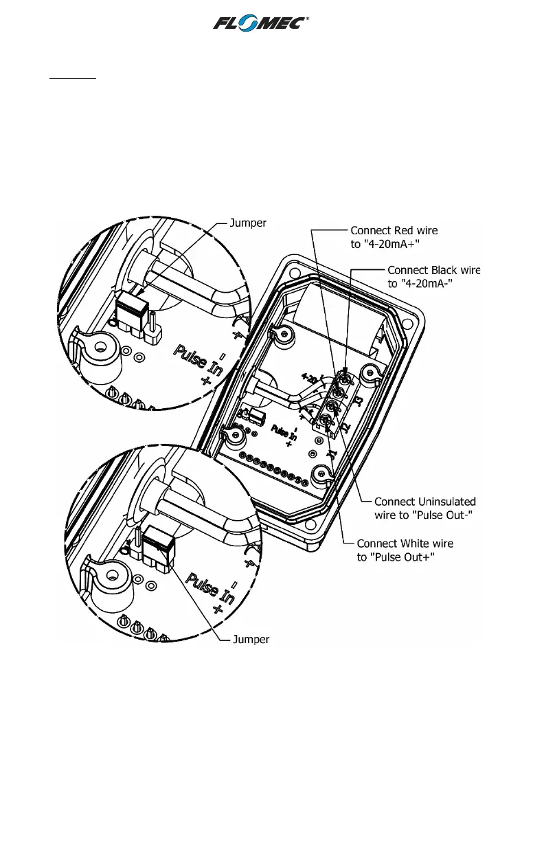
NOTE: The internal and external options for the pull up resistance and voltage is selectable
by the header on the 4-20mA board (see Figures 4a & 4b).
When the Jumper is on the top two pins, the “external resistor required” option is selected
(Figure 4a). This external resistor can be installed as shown on Figure 3, but could also be
built into the existing customer equipment.
When the Jumper is located on the bottom two pins, the “internal resistor” option is selected
(Figure 4b).
Figure 4a
Figure 4b

Other manuals for Flomec TM Series

Questions and Answers:

Question and Answer IconNeed help?

Do you have a question about the Flomec TM Series and is the answer not in the manual?

Flomec TM Series Specifications

General IconGeneral
BrandFlomec
ModelTM Series
CategoryMeasuring Instruments
LanguageEnglish

Related product manuals