9
INSTALLATION (Continued)
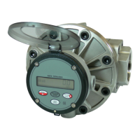
Wiring
The 4-20mA module comes pre-wired for external connections to external power and
provides an open collector output, which can be set to either raw or scaled pulse output. The
wires are color coded to connect as shown in Figures 3 & 4.
Wire Color Feature
Red 4-20mA (+)
Black 4-20mA (-)
White Pulse Out (+)
Uninsulated Pulse Out (-)
NOTE: The 4-20mA board provides a pulse output on the White wire with the cable shield
as the ground (return). This is set to raw pulse output as the default setting on the Q9 display.
If your application requires a scaling of the pulse output, refer to the installation instructions
to enable the scaled pulse feature and refer to the Q9 owner’s manual for instructions on the
configuration of the scaled pulse feature.
NOTE: If using the scaled pulse output feature, use the scaled K-factor in the user interface
device.
NOTE: The ground of the pulse output must be galvanically isolated from the 4-20mA loop
ground (return).
Figure 3