Installation 8
ELECTRICAL CONNECTIONS
Hazardous voltage. Can cause serious or
fatal electrical shock. Review safety instructions before
operating charger. Do not modify cord or plug.
CHARGER/BATTERY INSTALLATION
NOTICE: An alarm, located in the junction box, auto-
matically sounds when the system runs if the alarm is in
the “Enable” position. The alarm is silenced when the
alarm switch is in the “Disable” position.
Model Number FP1800DCC:
1. Apply two pieces of two-sided tape (provided, Key
No. 10) to the back of the junction box. Press the
junction box onto the battery box as illustrated in
Figure 5 and on Page 12 (Exploded View).
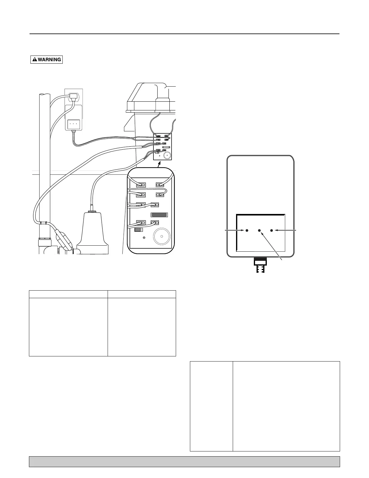
2. Connect the charger as shown in Table I and
Figure 5.
3. Plug the charger into a 115-120 Volt AC outlet deliv-
ering at least 15 amps. Do not use a switch con-
trolled outlet. Mark circuit in main power panel
“Backup sump pump power supply; do not turn off”.
4. With the charger properly connected and plugged in,
the panel on the front of the charger will show one
of the conditions illustrated in Figure 6.
Red LED - Fault indicator
See charge error table (Table II, below)
Yellow LED - Prequalification test stage is complete and testing
or charging in process
Green/Occasional Yellow - Charger turns on intermittently to
maintain proper charge
Green LED - Charging complete
NOTICE: For more detailed information, see “Charger Operation” on
Page 10.
BLACK TERMINAL NEGATIVE (-)
RED TERMINAL POSITIVE (+)
COMPLETE
CHARGE
FAULT
4 STAGE LEAD-ACID
BATTERY CHARGER
BATTERY CONNECTION
CHARGER CONNECTION
FLOAT SWITCH CONNECTION
REPLACE FUSE WITH SAME 25 AMP -
36V TYPE AND RATING ONLY
PUMP FUSE &
CONNECTION
DISABLE ENABLE
AUDIBLE ALARM
DISABLE WHEN LIT
+
+
+
–
–
–
BATTERY CONNECTION
CHARGER CONNECTION
FLOAT SWITCH CONNECTION
REPLACE FUSE WITH SAME 20 AMP -
36V TYPE AND RATING ONLY
PUMP FUSE &
CONNECTION
DISABLE ENABLE
AUDIBLE ALARM
DISABLE WHEN LIT
+
+
+
–
–
–
20
Figure 5 – Wiring Connections FP1800DCC
Connect the To the Junction Box’s
Positive (+) lead from the battery Positive battery connection
Negative (–) lead from the battery Negative battery connection
Positive lead from the charger Positive charger connection
Negative lead from the charger Negative charger connection
Backup sump pump Float switch
float switch (2 wires) connection (2 wires)
Positive lead from the pump Positive pump connection
Negative lead from the pump Negative pump connection
TABLE I - FP1800DCC Wiring Connections
BLACK TERMINAL NEGATIVE (-)
RED TERMINAL POSITIVE (+)
COMPLETE
CHARGE
FAULT
4 STAGE LEAD-ACID
BATTERY CHARGER
WARNING:
Risk Of Explosive Gas Mixture. Read
owner's instruction manual before using.
CAUTION:
Charge only lead-acid batteries. Other types may
burst causing personal injury and damage. Do not Expose unit to
rain or water. To prevent electric shock, dispose of charger if cord
becomes defective. Do not smoke, strike match or cause a spark
in the vicinity of battery during charging. Connect/disconnect
leads from battery only when charger is removed from AC
Power. Charge only in ventilated areas.
Green
Yellow
Red
Figure 6 – FP1800DCC LED Panel
Red LED is 1. A fault condition has occurred; indicates the
on continuously battery failed the prequalification test or
something went wrong during the charging
process.
2. AC power to charger, but no battery
connected. Charger output leads are
unconnected, but charger is plugged into
the AC receptacle.
3. Battery voltage is below 3 Volts; the
charger does not recognize the battery
and will therefore not charge.
4. Reverse battery condition; output leads
are connected backward on the battery.
5. Overcurrent condition; Something is being
powered by the battery while it is charging.
TABLE II - Charge Error Table for FP1800DCC
For parts or assistance, call Flotec Customer Service at 1-800-365-6832
 Loading...