Installation 9
For parts or assistance, call Flotec Customer Service at 1-800-365-6832
Model Number FP2800DCC:
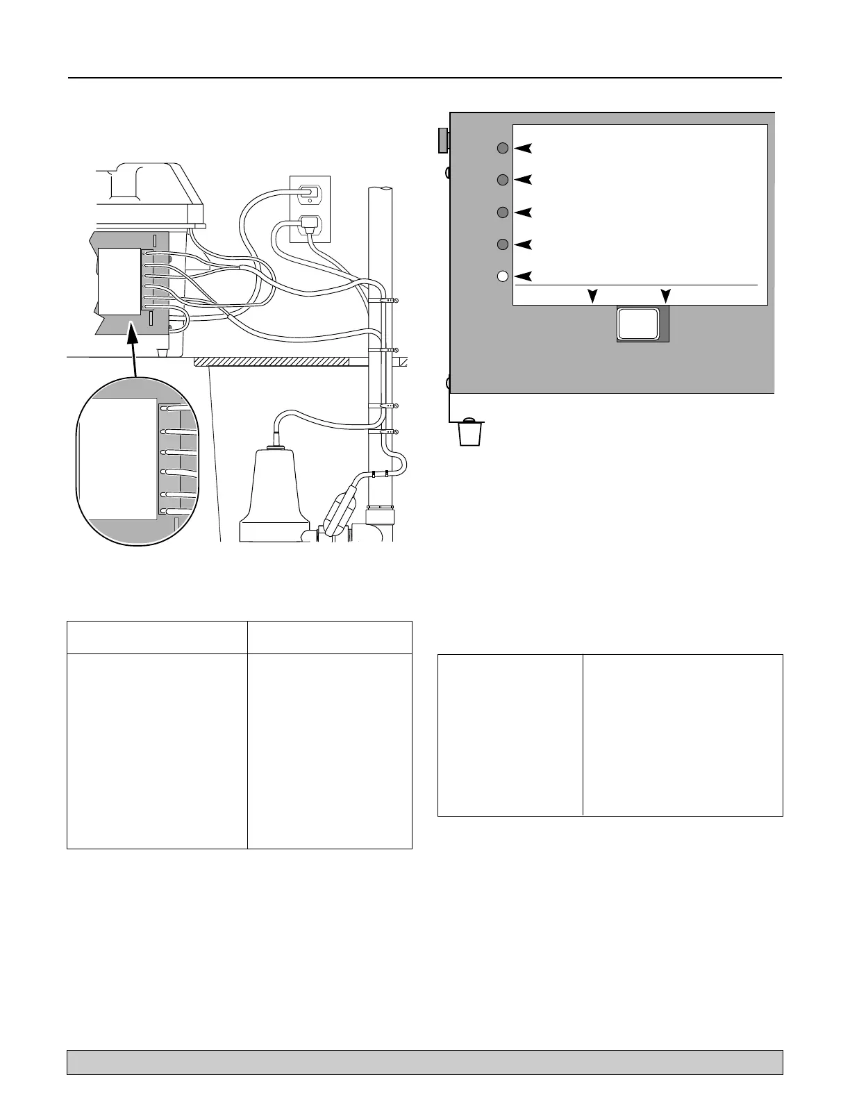
1. Connect charger as shown in Table III and Figure 7.
2. Plug the charger into a 115 Volt AC outlet delivering
at least 15 amps. Do not use a switch controlled
outlet. Mark the circuit in the main power panel
“Backup sump pump power supply; do not turn off”.
3. With the charger properly connected and plugged in,
the panel on the front of the charger will show one of
the following conditions (See Figure 8).
Red “AC Power On” LED - AC power is present
Yellow (bicolor) LED on continuously - Prequalification test is
complete and charging is in process.
Yellow “Charging” LED flashing on and off quickly. -
Equalization charge stage.
Green (bicolor) LED is on - Battery is being maintained at full
charge.
Bicolor LED flashing yellow/green alternatively - See Error
Charge Table (Table IV).
Test the Assembly:
1. Plug the primary pump into a properly grounded
3-prong outlet.
2. Fill the sump with water to start the primary pump.
Check for leaks.
3. Unplug the primary pump and fill the sump with
water to start the backup system pump. Check for
leaks.
4. Plug the primary pump back into a properly grounded
3-prong outlet. The system is now ready for operation.
CHARGER MODE
BATTERY STATUS
ÉTAT DE LA BATTERIE.
ESTADO DE LA BATERÍA.
MODE DU CHARGEUR.
MODO DE CARGADO.
ALARM SILENCE
ARRÉT D'ALARME.
SILENCIO DE ALARMA.
PUMP RUN
STATUS
ÉTAT DE FONCTIONNEMENT DE
LA POMPE.
ESTADO DE FUNCIONAMIENTO DE
LA BOMBA.
A.C.POWER
STATUS
3464 0799
ÉTAT DU COURANT ALTERNATIF.
ESTADO DE LA CORRIENTE ALTERNA.
SILENCE
ARRÉT/SILENCIO
ALARM
ALARME/ALARMA
RESET/RÉARMEMENT
REPOSICIÓN
Figure 8 – FP2800DCC LED Panel
Bicolor LED flashing Failed pre-qualification test.
Yellow/Green alternatively New battery may be needed
Red “Pump Run” Battery voltage is greater than
LED flashing expected
Red “Power” LED flashing Current is greater than expected
Bicolor LED and the Red One cell within the battery is
“Power” LED flashing overheating
Red “Power” and “Pump” Battery pack has taken too long to
LED’s flashing charge
TABLE IV - Charge Error Table for FP2800DCC
To the position indicated
Connect the below, on the charger
Positive (+) lead from the battery Positive battery terminal
(leads are provided)
Negative (–) lead from the battery Negative battery terminal
(leads are provided)
Positive (+) “Backup sump Pump” Positive pump lead terminal
lead (BROWN wire)
Negative (–) “Backup sump Pump” Negative pump lead terminal
lead (BLACK wire)
Positive (+) Float switch Lead Positive float switch terminal
(WHITE wire)
Negative (–) Float Switch Lead Negative float switch terminal
(BLACK wire)
TABLE III - FP2800DCC Wiring Connections
PUMP/POMPE/BOMBA (+)
PUMP/POMPE/BOMBA (–)
FLOAT/FLOTTEUR/FLOTADOR (+)
BATTERY/BATTERIE/BATERÍA (–)
BATTERY/BATTERIE/BATERÍA (+)
FLOAT/FLOTTEUR/FLOTADOR (–)
PUMP/POMPE/BOMBA (+)
PUMP/POMPE/BOMBA (–)
FLOAT/FLOTTEUR/FLOTADOR (+)
BATTERY/BATTERIE/BATERÍA (–)
BATTERY/BATTERIE/BATERÍA (+)
FLOAT/FLOTTEUR/FLOTADOR (–)
Figure 7 – Wiring Connections FP2800DCC