INSTALLATION, OPERATION, &
MAINTENANCE MANUAL
TITLE: F7000 / 8000 Series Rev. T
Pilot-Operated Safety Relief Valve Page 18 of 43
B. F300 (Diaphragm-style) Assembly
NOTE: Exercise care in handling softgoods, nozzles, and other sealing surfaces.
1) Confirm pressure setting and associated parts required.
2) Place the valve body in a vise.
3) Install pipe plugs into the valve body.
4) Install backflow preventer (BFP) O-ring onto BFP piston.
5) Insert BFP piston assembly into valve body.
6) Assemble BFP jam nut and seal onto BFP nozzle. For modified nozzle design with 00-2313-xx
O-ring on leading edge, install O-ring with light coat of lubricant to hold it in place.
7) Install backflow preventer assembly into valve body until very tight (conventional chamfered nozzle)
or snug (O-ring-tipped nozzle), then tighten BFP jam nut so as to crush the seal.
8) Assemble lock nut and proporational band screw seal onto proportional band screw.
9) Install the proportional band screw assembly into the valve body. Screw in CW until the screw
bottoms in the body, and then back out CCW 1-1/2 turns (also see Section 6.3 for band screw
adjustment). Tighten lock nut.
10) Insert inlet screen into valve body.
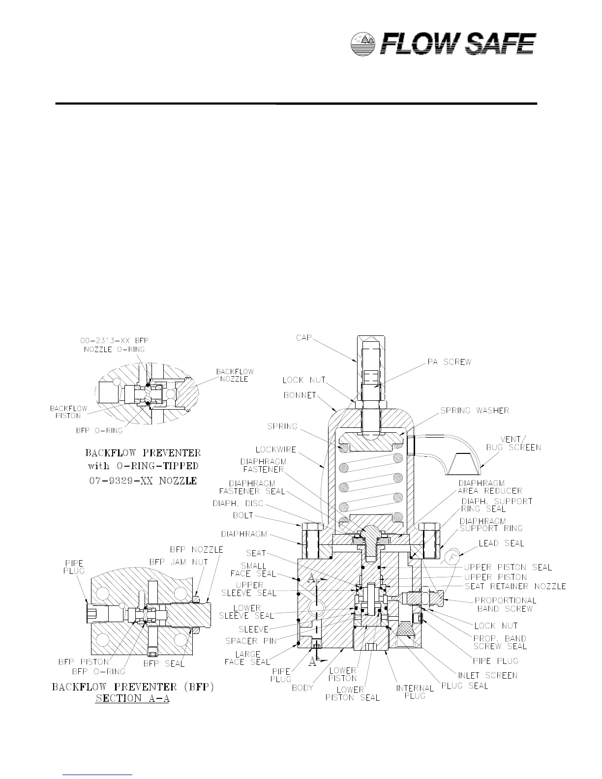
F300 PILOT VALVE ASSEMBLY – HP DIAPHRAGM-STYLE (286 - 500 psig)
 Loading...